 Using the Module
The wood roof ties calculator is capable of designing the ties and rafter for a gable roof having any combination of collar ties, rafter ties, or ridge straps. All load combinations are checked, and both uplift and downward forces are considered. Using the calculator involves three essential steps, and one optional step in which the design can be fine-tuned.
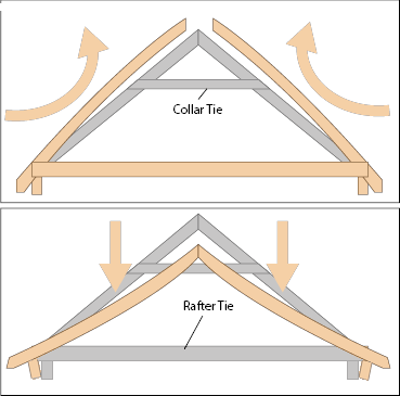
In the design of a gable roof, ties serve two purposes, as illustrated in the graphic on the right:
- Ties prevent the rafters from separating at the ridge in wind uplift loads; and
- Ties prevent the walls from being pushed outwards by the roof under downward or gravity loads.
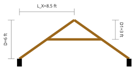
1. Geometry Inputs
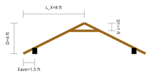 The first step in using the calculator is to input the overall geometry. The diagram, an example of which is shown to the right, will update dynamically as each of the inputs are set. These inputs include:
- Rafter Plan Length: The horizontal length of a single rafter. Usually, this will be half the width of the roof, from eave to ridge. This is the horizontal plan length, which will only equal the total rafter length if the roof pitch is zero (flat).
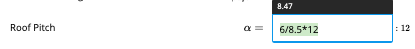
- Roof Pitch: The rise over run pitch of the roof, given in the form of “x:12”.
- Ridge Strap Present?: A ridge strap is a metal strap which runs over the top of the roof and connects rafters on either side of the rafter. Note that this module does NOT design the ridge strap itself; it is simply assumed that the ridge strap is of sufficient strength to keep the rafters connected at the ridge under any uplift conditions.
- Number of Ties Present: This refers to collar ties or rafter ties. If both are present, then select “Two”, otherwise select “One”.
- Depth of First/Second Tie: The depth of the collar and/or rafter tie from the roof ridge to the tie. Note that, if there are two ties, it does not matter which tie is the “first” or “second”, as long as it remains consistent throughout
- Eaves & Rafter Supports: The length of the eave, equal to the distance between the edge of the rafter and the wall, as well as the bearing length of the wall, are set in one table. For the purpose of bearing calculations, the supports are assumed to be eclusively on the rafter, not any of the ties.
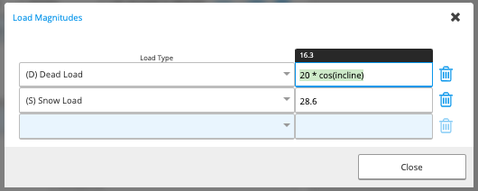
2. Enter Loads
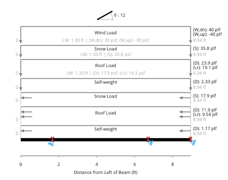 The calculation is pre-filled with the roof loads, snow loads, and wind loads, an example of which is shown on the right. It is likely that none of this will need to be updated, as the default load magnitudes and rafter spacing are all pulled directly from the Project Defaults.
3. Member Selection
 The rafter member and each of the ties are set in the next sections. Members may be selected from our database of standard sections, or a custom rectangular section may be defined with any species, grade, and dimensions.
Design can be a breeze by using our member selector or autosize features.
The rafter member and each of the ties are set in the next sections. Members may be selected from our database of standard sections, or a custom rectangular section may be defined with any species, grade, and dimensions.
Design can be a breeze by using our member selector or autosize features.
Worked Examples
Two worked examples are provided here: one of gravity forces only, and one of a wind uplift scenario. Both are simplified examples, but should be illustrative of the usage of this module.Gravity Loading Only Example
 A roof is to be designed having the following geometry and loads:
- Total roof width = 17 ft, with no eaves
- Total roof height = 6 ft
- Tie depth = 3 ft (mid-height)
- Dead load = 20 psf on a horizontal plan area, including self-weight (equals 16.3 psf on a sloped area)
- Snow load = 35 psf on a horizontal plan area (equals 28.6 psf on a sloped area)
- Tributary width = 16 in
 The tie depth can be entered as it’s given, simply as “3 ft”. Finally, the module defaulted to an eave length of 1.5 ft, as would be typical for many houses, but in this problem, there are no eaves - so the eave length should be changed to “0 ft”.
For loads, the Calcs.com platform applies the magnitudes over a sloped area, not over a horizontal plan area. While entering “20 psf” and “35 psf” would be conservative, it would be overly conservative for this design. To convert a horizontal plan area load to a sloped area load, the magnitude needs to be multiplied by the cosine of the slope. This math can be done outside of the platform, but Calcs.com also allows the user to enter formulas, so this can be entered as the following, for example:
The tie depth can be entered as it’s given, simply as “3 ft”. Finally, the module defaulted to an eave length of 1.5 ft, as would be typical for many houses, but in this problem, there are no eaves - so the eave length should be changed to “0 ft”.
For loads, the Calcs.com platform applies the magnitudes over a sloped area, not over a horizontal plan area. While entering “20 psf” and “35 psf” would be conservative, it would be overly conservative for this design. To convert a horizontal plan area load to a sloped area load, the magnitude needs to be multiplied by the cosine of the slope. This math can be done outside of the platform, but Calcs.com also allows the user to enter formulas, so this can be entered as the following, for example:
 Note that the problem says that self-weight is already included in the given dead load magnitude, so change “Include Self-Weight” to “No”, and then the calculation is done! The optimal members can then be selected. Our member selector or autosize features can be used to quickly select the optimal rafter and tie sizes, or they can be manually selected in the relevant fields. A 2x10 Hem-Fir No. 1 works for the rafter, and a 2x4 Hem-Fir No. 1 easily works for the tie.
A full printout of this example using the ASD module can be downloaded here: Downward Roof Tie Example (note that this is the “Standard” print mode; one-page or full detailed print modes are also available)
Note that the problem says that self-weight is already included in the given dead load magnitude, so change “Include Self-Weight” to “No”, and then the calculation is done! The optimal members can then be selected. Our member selector or autosize features can be used to quickly select the optimal rafter and tie sizes, or they can be manually selected in the relevant fields. A 2x10 Hem-Fir No. 1 works for the rafter, and a 2x4 Hem-Fir No. 1 easily works for the tie.
A full printout of this example using the ASD module can be downloaded here: Downward Roof Tie Example (note that this is the “Standard” print mode; one-page or full detailed print modes are also available)
Wind Uplift Example
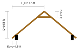 A roof is to be designed having the following geometry and loads:
- Rafter plan length = 11.5 ft, with 1.5 ft eaves
- Roof pitch = 10 : 12
- Tie depth = 2 ft
- Dead load = 10 psf on a sloped plane, including self-weight,
- Wind uplift load = 40 psf
- Tributary width = 16 in
 For loads, the dead load is in the direction of gravity, but the wind is always perpendicular to the roof. Therefore, the “Orientation” column is important to set, and the dead load and wind uplift load must be added in separate rows in the table, as shown on the right. Also, the wind uplift is in an upwards direction, and therefore must be entered as a negative number.
The optimal members may be then be selected, and again, the member selector or autosize features can make this a breeze. A 2x12 Southern Pine No. 1 works for the rafter, and a 2x4 Southern Pine No. 1 easily works for the tie.
A full printout of this example using the ASD module can be downloaded here: Uplift Roof Tie Example (note that this is the “Standard” print mode; one-page or full detailed print modes are also available)
For loads, the dead load is in the direction of gravity, but the wind is always perpendicular to the roof. Therefore, the “Orientation” column is important to set, and the dead load and wind uplift load must be added in separate rows in the table, as shown on the right. Also, the wind uplift is in an upwards direction, and therefore must be entered as a negative number.
The optimal members may be then be selected, and again, the member selector or autosize features can make this a breeze. A 2x12 Southern Pine No. 1 works for the rafter, and a 2x4 Southern Pine No. 1 easily works for the tie.
A full printout of this example using the ASD module can be downloaded here: Uplift Roof Tie Example (note that this is the “Standard” print mode; one-page or full detailed print modes are also available)
Theory Guide
The module consists of two major portions: analysis and design.Design
The design of the rafter is exactly the same as that used in our regular Wood Beam calculators; details on this methodology are described in detail in the Wood Beam article, and will not be repeated here. For ties, because the module does not allow load to be applied directly to the ties, the ties are definitionally in pure tension (ignoring self-weight, which is negligible for the purpose of design). Tie design therefore adjusts the base tension strength with the following adjustment factors:- Duration Factor (for ASD), or Time Factor and Format Conversion Factor (for LRFD)
- Wet Service Factor
- Incising Factor (for dimensioned lumber and timber only)
- Size Factor (for dimensioned lumber and timber only)
Analysis
There are two methods that could be used for analyzing a tied roof: either a full truss analysis, or an advanced beam analysis with oriented roller supports. While a full truss analysis would be able to handle more loading scenarios, it also introduces an unnecessary level of complexity, and this module therefore uses the latter method of an advanced beam analysis. That beam analysis looks at a single rafter in isolation (assuming that the left and right rafters are identical), with two possible support conditions depending upon whether the total loads result in a net uplift or net downward force:Net Gravity / Downward Force
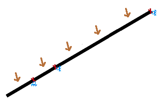 In a net downward force, the gable roof will tend to try and push the walls apart, and a tie serves the purpose of preventing this and holding the rafters at their original roof pitch. Usually, a tie used for this purpose is usually called a “rafter tie”, and it is most efficient to place such a rafter tie in the lower third of the roof (at a relatively large depth below the ridge).
In this configuration, shown on the right, the beam model is supported by three roller supports. The bottom most support is oriented such that it can roll horizontally but not vertically, and represents the wall. The top-most support is the ridge, with a vertically-oriented roller support, representing the fact that the opposite rafter will prevent this one from moving to side-to-side, but nothing prevents the ridge from moving up and down. Finally, the middle support is a tie, which is also a vertically-oriented roller because it has no ability to prevent movement up and down, but does restrain the roof from splaying apart.
The reaction at the tie support is equal to the tension in the tie, and the reaction at the bottom-most wall support is used in bearing calculations.
In a net downward force, the gable roof will tend to try and push the walls apart, and a tie serves the purpose of preventing this and holding the rafters at their original roof pitch. Usually, a tie used for this purpose is usually called a “rafter tie”, and it is most efficient to place such a rafter tie in the lower third of the roof (at a relatively large depth below the ridge).
In this configuration, shown on the right, the beam model is supported by three roller supports. The bottom most support is oriented such that it can roll horizontally but not vertically, and represents the wall. The top-most support is the ridge, with a vertically-oriented roller support, representing the fact that the opposite rafter will prevent this one from moving to side-to-side, but nothing prevents the ridge from moving up and down. Finally, the middle support is a tie, which is also a vertically-oriented roller because it has no ability to prevent movement up and down, but does restrain the roof from splaying apart.
The reaction at the tie support is equal to the tension in the tie, and the reaction at the bottom-most wall support is used in bearing calculations.
Net Uplift Force
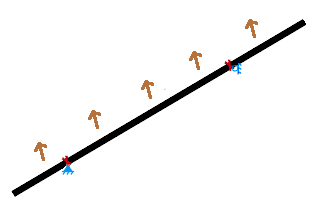
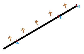 In a net uplift force, a gable roof will tend to stay in place at its bottom, but will try to split apart at the ridge. Either a tie or a ridge strap may be used to prevent the rafters from separating at the ridge. A tie used for this purpose is usually called a “collar tie”, and it is most efficient to place it in the top third of the roof (at a relatively small depth below the ridge).
There are two possible support configurations for the net uplift condition, depending upon whether or not a ridge strap is present. Both configurations, shown on the left, have a pinned support at the bottom, representing a wall which does not move in any direction.
If a ridge strap is NOT present, as in the far left configuration, then there is only one other support, which represents the collar tie. That collar tie does nothing to restrict the up and down movement of the roof, but does hold the rafters together, and is therefore a vertically-oriented roller support.
If a ridge strap IS present, as in the second configuration, then an additional support is added at the ridge. This support is also a vertically-oriented roller, because the ridge strap does not prevent up and down movement, but does prevent the rafters from separating.
The reaction at the tie support is equal to the tension in the tie.
In a net uplift force, a gable roof will tend to stay in place at its bottom, but will try to split apart at the ridge. Either a tie or a ridge strap may be used to prevent the rafters from separating at the ridge. A tie used for this purpose is usually called a “collar tie”, and it is most efficient to place it in the top third of the roof (at a relatively small depth below the ridge).
There are two possible support configurations for the net uplift condition, depending upon whether or not a ridge strap is present. Both configurations, shown on the left, have a pinned support at the bottom, representing a wall which does not move in any direction.
If a ridge strap is NOT present, as in the far left configuration, then there is only one other support, which represents the collar tie. That collar tie does nothing to restrict the up and down movement of the roof, but does hold the rafters together, and is therefore a vertically-oriented roller support.
If a ridge strap IS present, as in the second configuration, then an additional support is added at the ridge. This support is also a vertically-oriented roller, because the ridge strap does not prevent up and down movement, but does prevent the rafters from separating.
The reaction at the tie support is equal to the tension in the tie.
A Few More Notes
- Of course, ties don’t magically appear or disappear depending upon whether the net force is upward or downward. If there are two ties present, then two ties will be present in both uplift and downward configurations, and if only one tie is present, then that tie is going to resist loads regardless of the direction of net force, even if it’s inefficient in one of the directions.
- Internally, both uplift and downward configurations are always run; two FEA models will always exist in the background. In compiling the analysis results, the module will check whether the total force on the rafter is upwards (negative total load) or downwards (positive total load), and pull results from the correct model accordingly. If there is no load combination in which a net uplift occurs, then no results from the uplift model will be included in the final demands.
- A keen observer may note here that it is possible to have an upwards movement of the ridge if an applied moment load is applied, or if a particularly high downwards load is applied on the eave. It is for this reason that, unlike other Calcs.com modules, this module forbids any applied moment loads from being added. It is further listed as an assumption that eave loads are not sufficient to cause uplift at the ridge, though it is left to the user to verify this very rare possibility does not occur.
Reading the ridge strap tension result
When Ridge Strap Present? is set to Yes, the analysis adds a vertically-oriented roller support at the ridge to represent the strap. The reaction at that ridge support equals the tension force in the ridge strap under net uplift load combinations. You can read this value off the calculator as follows:- Open the Reactions section of the calculator output. The ridge support is the top-most support in the table (it sits at depth 0 from the ridge).
- The value reported under the governing uplift load combination is the tension demand on the ridge strap, per rafter pair, in the units set on the project.
- Because the ridge strap itself is not designed by this module, this reaction is the demand you should hand off to your strap manufacturer’s allowable tension capacity (e.g. a Simpson Strong-Tie or similar pre-engineered strap), already factored for the load combination shown.
- The value is only meaningful for load combinations where the net force on the rafter is upward. For net-downward combinations, the ridge strap is in compression-which the strap cannot resist-and the module instead transfers load through the collar/rafter tie.
- The reported reaction is per rafter pair (one strap spanning between two opposing rafters at the ridge), not per linear foot of ridge. Multiply by your rafter spacing only if your strap is rated as a line load.
- If both a ridge strap and a collar tie are present, the strap and the tie share the uplift demand based on their relative positions in the FEA model. The tie’s tension is shown in the tie design section; the strap’s tension is shown in the ridge reaction.