Background
Every Calcs.com project has a button in the sidebar called ‘Project Defaults’. These are a set of default/preset values that are used by the various calculators we offer. They are carried through to every new calculation that is created. The purpose of this guide is to clarify the use of these defaults, and which calculators are impacted by each option. You can still override any of these defaults in a specific calculator by selecting the field in question and manually typing over it. These defaults are purely to save you time, and you don’t need to use them if you don’t want to. If you copy a project, any project defaults will be copied along with the calculations. The main sections in Project Defaults are:- Design criteria / Load Combinations (e.g. default deflection limits, design code)
- Building geometry (e.g. beam spacings, story heights, roof slope)
- Default Loads (e.g. default roof, floor, wall & window loads)
- Load combinations (e.g. standards based, custom)
1. Design Criteria
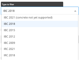
1(A) Design Code for Load Combinations
This dropdown provides a choice of standards / clauses to use to determine load combinations. You may also select “Custom load combinations” at the bottom of the drop downs and enter custom combinations. Refer article: 141-change-or-create-custom-load-combinations. Why would you want to set custom combinations?- Your company designs to more strict combinations than the code requires
- Calcs.com does not yet include amendments from your local state / area code
1(B) Deflection Criteria
Deflection limits may be set that will be defaulted in all calculators where applicable. Deflection limits are set for each of short-term loads, long-term loads, and a simplified deflection dead & live load criterion. A hard limit is provided which overrides any span limits, which may also be set (e.g. set a deflection limit to the minimum of 2 inches or L/360).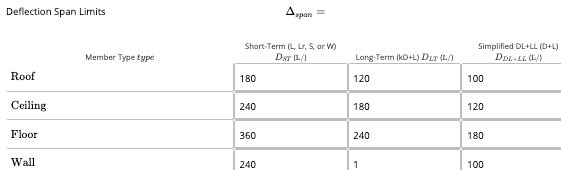 There are a few criteria that will affect the default deflection limits in the above table depending on your building code. (IBC / IRC / California BC&RC only).
1(C) Default Bearing Length
A bearing check is completed for wood beams. This length is along the length of the beam (i.e. length of supporting member/column). For general residential projects, this should be set as the width of your top plates or the hangers where your joists will bear.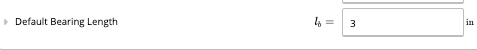
2. Building Geometry
2(A) Number of Stories
Where 2 or more stories, additional options will be provided for “Lower Floor” heights as well as “Top Floor”. Note this is typically used with the CalcsCAD tool only.
2(B) Roof Slope
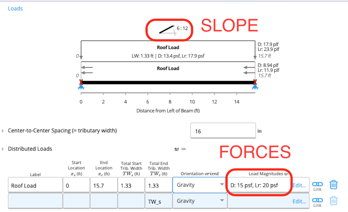
The slope of the roof (in inches per foot) is set on all calculators for the design of roof components, and for the beam and wind analysis calculators. This value CAN be changed in individual rafter calculators if roof slopes differ throughout your project.
2(C) Rafter / Joist / Wall studs Spacing
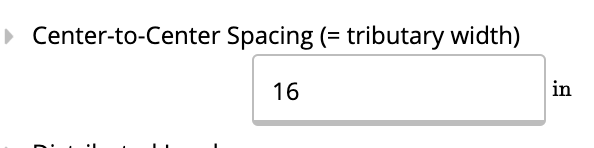
Spacings are used to calculate default distributed loads in rafters and joists. Refer to our article 170-what-is-tributary-width for details about how distributed loads are calculated.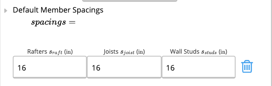 Quick Tip: Did you know that rafters or joists may be linked into other beams (e.g. floor bearer) as a line load? This means you only have to create a single rafter / joist and then Calcs.com will use the spacing to regularly space the reactions. Refer for details 24-linking-reactions-between-beams-and-columns-load-path-tracking. Of course the values may be overridden within each calculator. See example from the “Steel Beam” calculator:
2(D) Story Height / Headroom / Roof Beam Depth
Default heights for most columns (depends on if column is part of a typical light framing or heavy framing system). The window height parameter is used to calculate the weight of the wall above headers.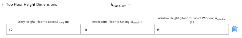
3. Default Loads
3(A) Roof
Default criteria and loading to apply to all roof beams. The “Default Roof Loads” table is then used as the default values in a number of calculators as listed. Note that by default, we currently don’t calculate a live load reduction accounting for roof slope which is allowed per some building codes, including the International Building Code 2018 (see Clause 1607.13.2.1).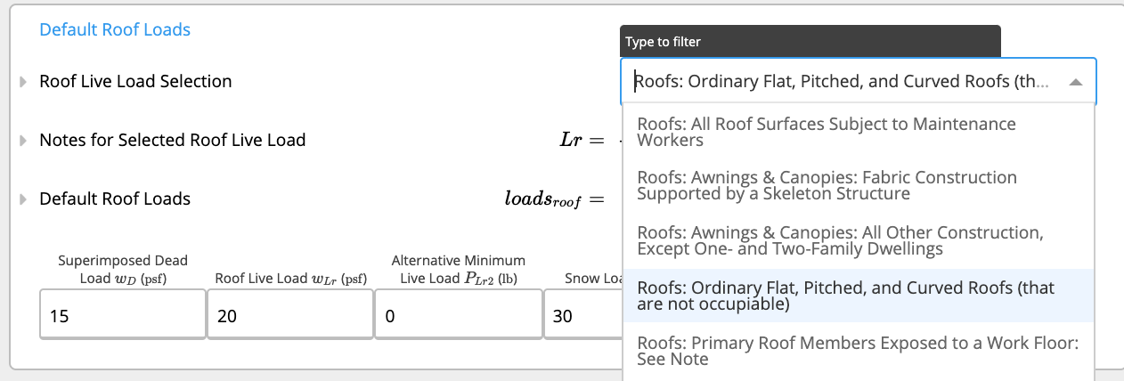
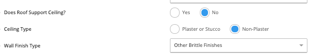
3(B) Ceiling
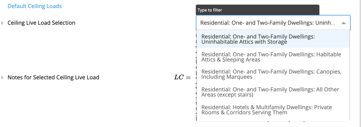
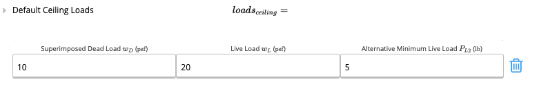
Ceilings have default area loads depending on the structures’ intended use.The “Ceiling Live Load Selection” is used to set the “Default Ceiling Loads” details in the dropdown menu.
These are obtained from IBC 2021, Table 1607.1 & ASCE 7-16, Table 4.3-1. Note that depending on the anticipated use of the attic, the duration factor on wood ceiling joists will vary between storage loads (CD = 0.9) and live loads (CD = 1.0). By default, our ceiling joist presets consider the attic loads as storage loads.
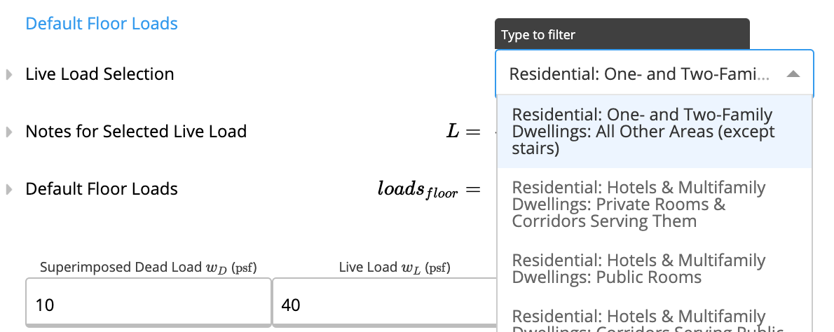
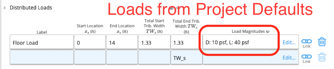
3(C) Floor
Floors have default area loads depending on the structures’ intended use.The “Live Load Selection” is used to set the “Default Floor Loads” details in the dropdown menu.
These are obtained from IBC 2021, Table 1607.1 & ASCE 7-16, Table 4.3-1. Again, note that we currently don’t perform any calculations for live load reduction.
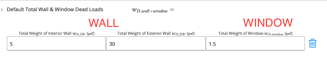
3(D) Wall & Window
WallWall loads can be manually set.When used in a calculator, the wall weight below is multiplied by the height of wall above the structure (e.g full height wall for floor headers) and entered as a Distributed Load.
To modify the “height of the wall above the structure” adjust the story height in “Design Criteria” section. Window
The window area load can be manually set below.
When used in the Wall Analysis with Load Combinations calculator, the window weight is added to the Self-weight of the structure and may be overridden in the “SW_Window” input.
3(E) Railing
For a Wall Analysis (Railing), the height of the wall is defaulted to the height of the railing. It may be overridden in the “h_wall” input field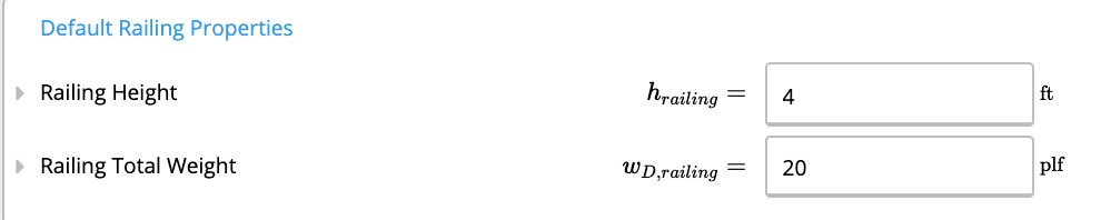
|AFFECTED CALCULATORS|
|---| |Wall Analysis with Load Combinations (Railings)|4. Custom Load Combinations
4(A) Exclude L2 from Load Linking
Our load linking feature is documented here:24-linking-reactions-between-beams-and-columns-load-path-tracking
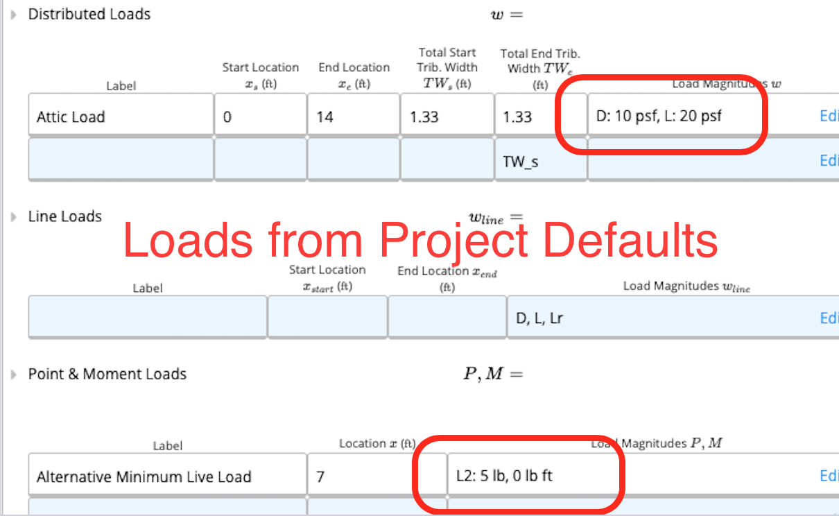
 Each calculation has “alternative” live load combinations, which are not intended to be applied at the same time (e.g. in many cases, codes require to take the worst of a uniform load OR a point load at midspan)). These are represented by L and L2. When linking loads, you can choose to only transfer through the main load (i.e. the alternative load does not need to be applied to others parts of the structure).
Generally this load shouldn’t actually be linked through the load path in the building - it should just be an alternate load for individual members only. Select “Yes” here to exclude these loads from all load linking throughout this project.
Each calculation has “alternative” live load combinations, which are not intended to be applied at the same time (e.g. in many cases, codes require to take the worst of a uniform load OR a point load at midspan)). These are represented by L and L2. When linking loads, you can choose to only transfer through the main load (i.e. the alternative load does not need to be applied to others parts of the structure).
Generally this load shouldn’t actually be linked through the load path in the building - it should just be an alternate load for individual members only. Select “Yes” here to exclude these loads from all load linking throughout this project.
Congratulations! You’ve reached the end of this guide.