Background Information
This example demonstrates wind load calculations for a barn designed to store agricultural goods in Bernardsville, New Jersey. The calculations follow the Envelope Procedure in ASCE 7-16, determining the wind pressures acting on the barn’s walls and roof for Main Wind-Force Resisting Systems (MWFRS) using the Wind Loads (ASCE 7-16) calculator. The barn is located on a flat, open, and isolated site. Its building footprint measures 24 ft by 40 ft (7.32 m by 12.19 m), with a gable roof pitched at 9:12. The eave height is 12 ft (3.66 m), and the total height from the ground to the ridge is 21 ft (6.4 m). This example is sourced from the McGraw Hill Textbook, Building Design for Wind Forces, 1st Edition, authored by Rima Taher, Ph.D., P.E., and can be found on AccessEngineering.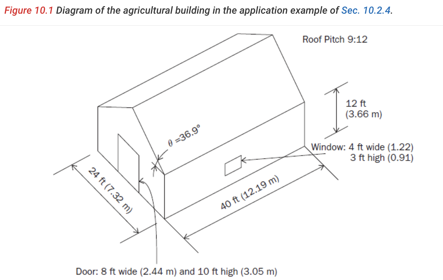
Project Defaults
In the Project Defaults section, you can enable the Override Project Defaults option by selecting Yes to manually enter the Basic Wind Speed for your project. Otherwise, our system will automatically calculate the Basic Wind Speed based on the project’s address and risk category, if these details are provided. For this example, Agricultural buildings fall under Risk Category I. We will manually input the Basic Wind Speed since the exact location is unavailable. The Basic Wind Speed is set to 105 mph, based on the ASCE 7-16 wind speed map for Risk Category I. In this example, we will analyze the MWFRS (Main Wind-Force Resisting System) using the Envelope Method, so we will select this option in the calculator. The Exposure Category is C (open terrain with scattered obstructions).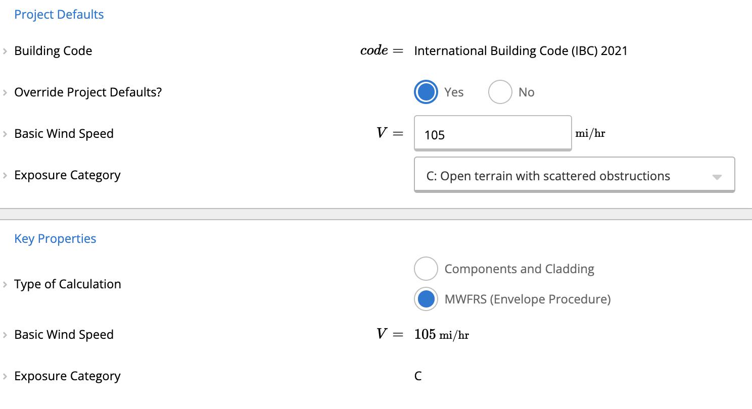
Building properties:
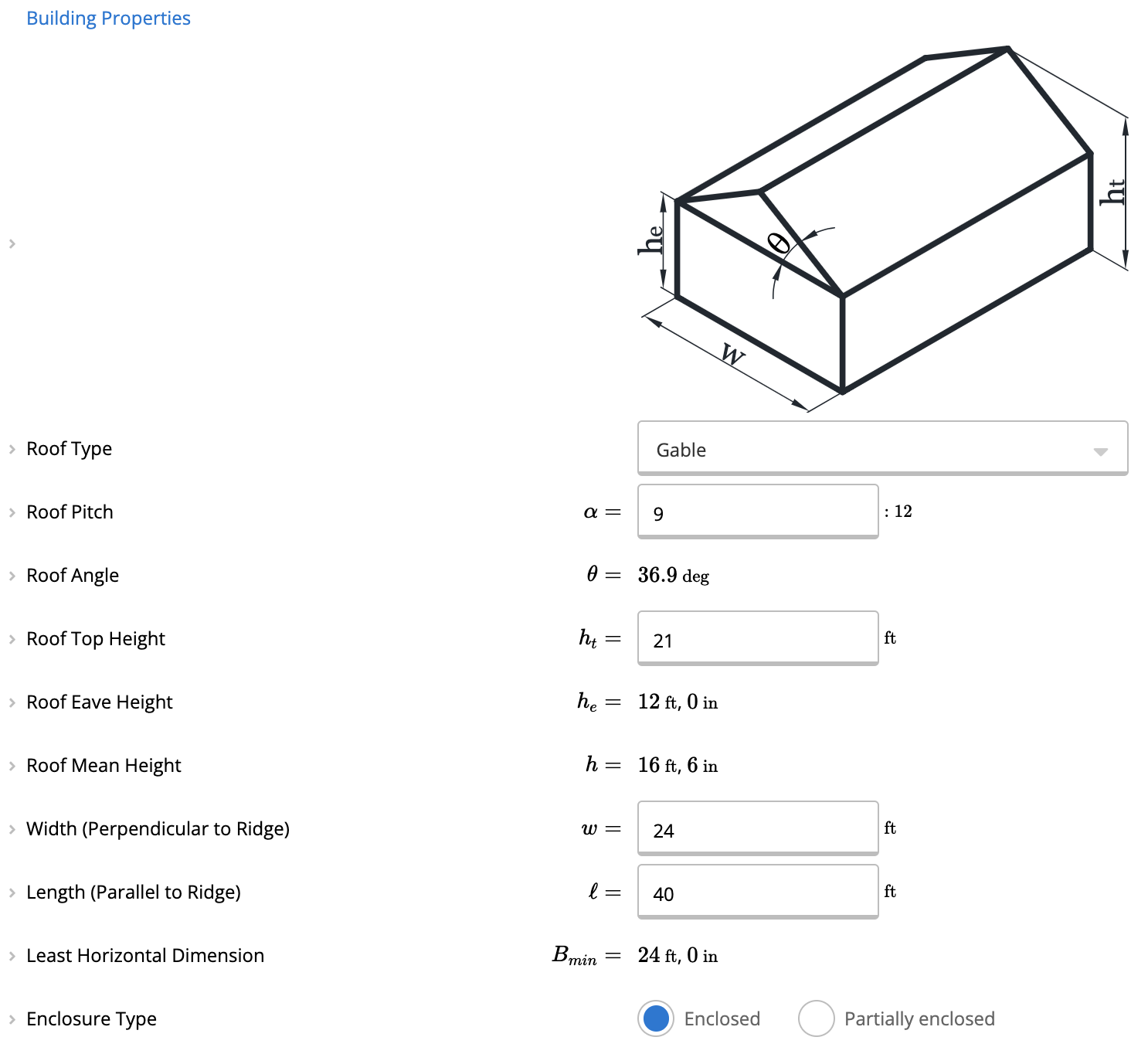
In the Building Properties section, you can enter the dimensions for this example. You can find these details in the image below.- Roof Type: Gable
- Roof Pitch: 9:12
- Roof Top Height: 21 ft (6.4 m)
- Footprint Dimensions: Width 24 ft by Length, 40 ft (7.32 m by 12.19 m)
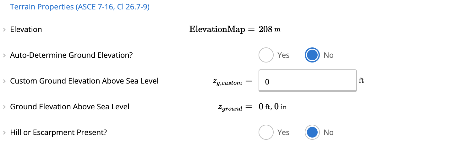
 In Calcs.com, you can enter your project’s location when creating it. This allows the calculator to automatically determine the ground elevation above sea level if you prefer, which will be used to calculate the elevation factor (Ke). However, for this example, you can select the option No, since there is no exact location of the project. By doing this, a value of Ke = 1.00 will be used, as permitted by the ASCE 7-16 standard, which allows this conservative approximation for all cases.
Wind Load Parameters
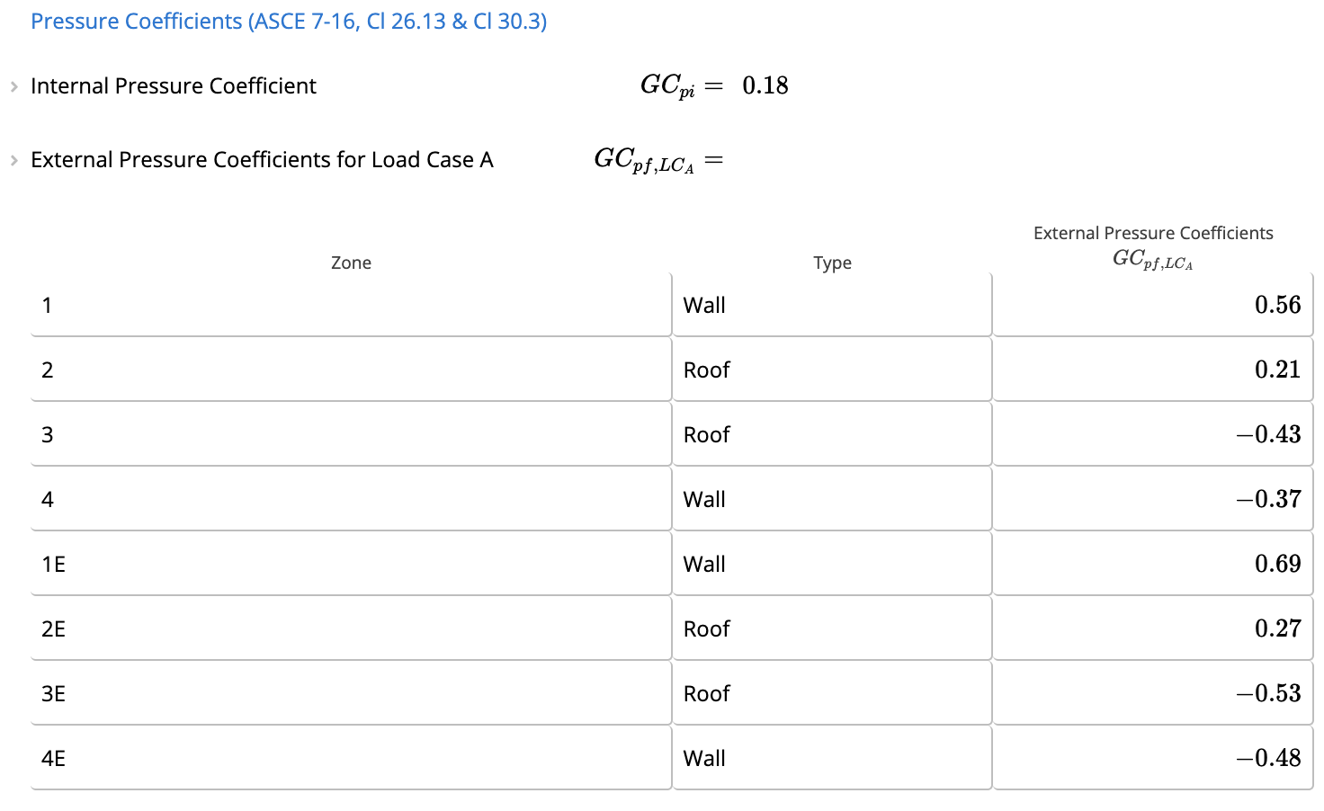
Once you’ve entered the inputs mentioned, you’ll be able to view the Wind Load Parameters. These parameters are automatically calculated based on the information provided, ensuring accurate and code-compliant results for your project.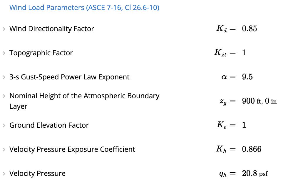 In this section, you’ll see the Pressure Coefficients for wind loads. These include:
- Perpendicular Pressure Coefficients for wind loads acting perpendicular to the ridge (Load Case A).
- Parallel Pressure Coefficients for wind loads acting parallel to the ridge (Load Case B).

Results
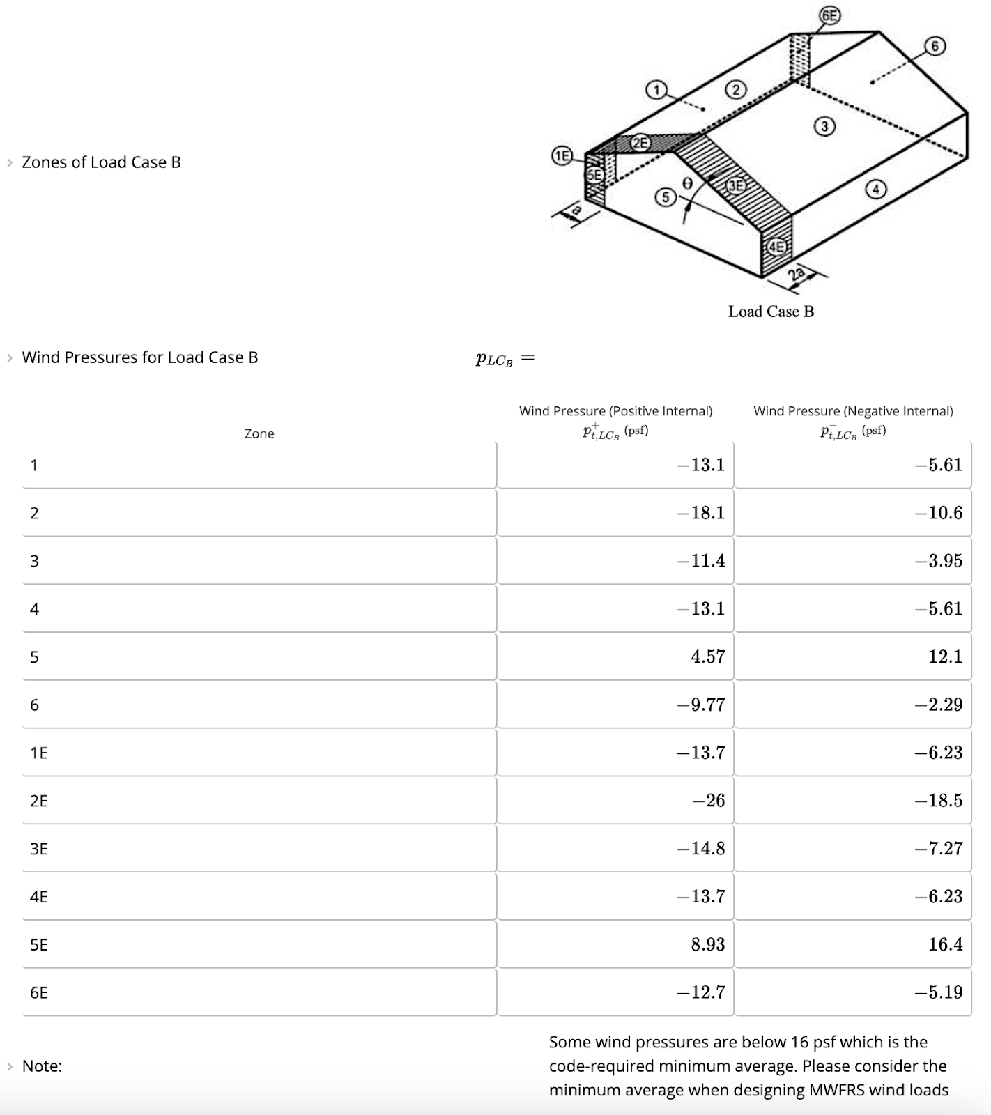
In the Summary Section, you’ll find the wind pressures calculated for both Load Case A (perpendicular to the ridge) and Load Case B (parallel to the ridge). This provides a clear overview of the pressures applied to the building under different wind load scenarios, ensuring you have all the information needed for your design.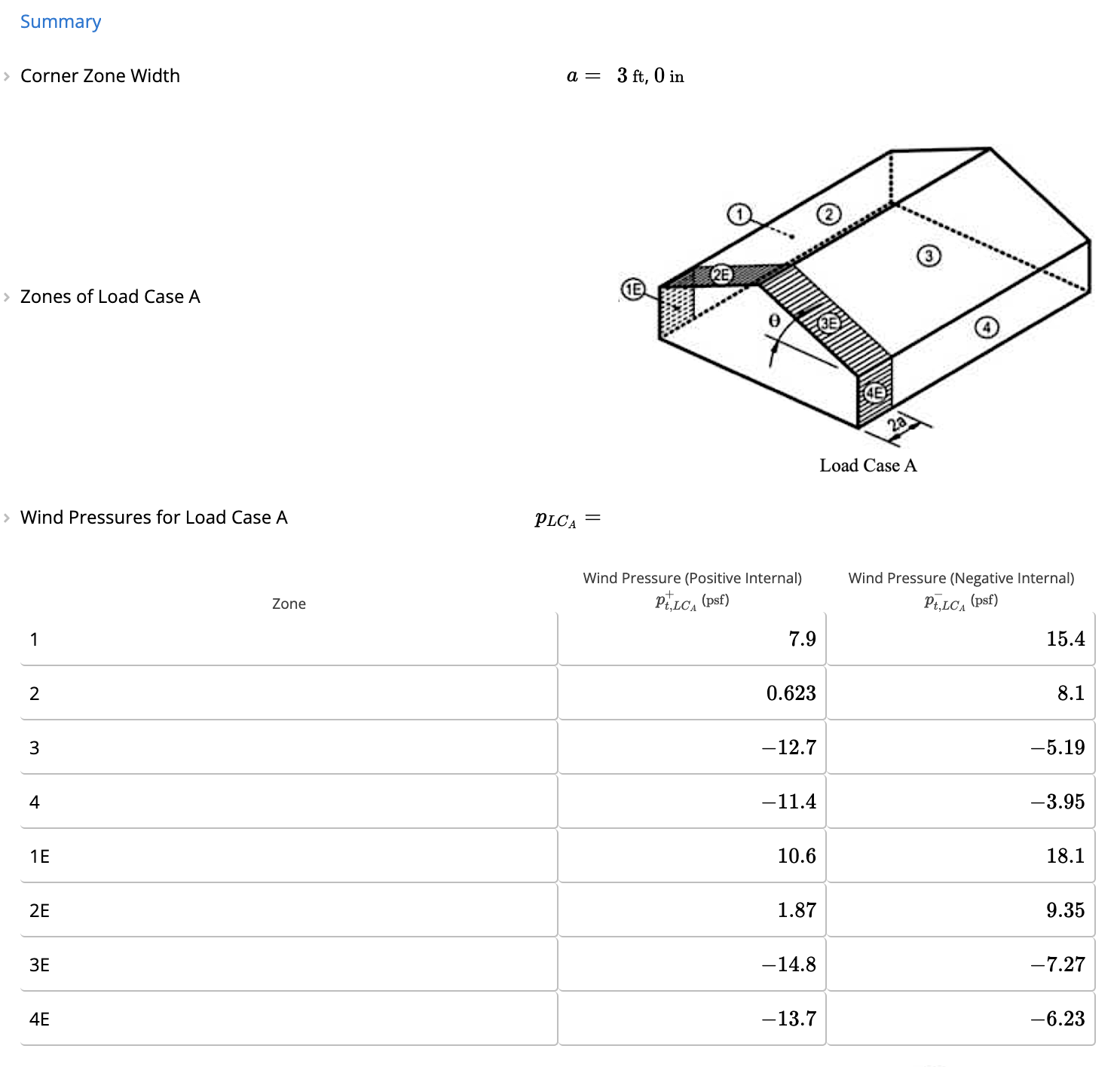
Linking to Diaphragms:
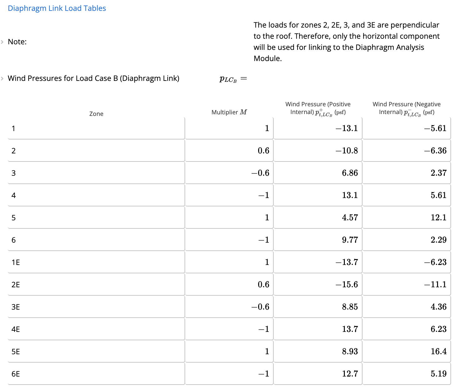
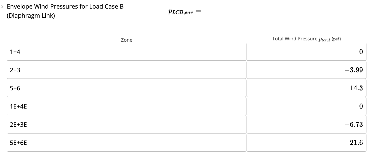
In this section, once you have determined the wind pressures, you have the option to link the wind loads to the Diaphragm Analysis (Load Linking) calculator . You can select which load case to link—A or B. You would typically link Load Case A for the diaphragm calculations spanning parallel to the ridge, and Load Case B for the ones spanning perpendicular to the ridge. By choosing the “Simple” linking type, you can link the total or global pressures, which combine local zone pressures under the assumption that internal pressures cancel each other out. This simplifies the process by eliminating the need to differentiate between positive and negative values. Alternatively, selecting the “Advanced” linking type allows users to individually assign wind pressures to the Diaphragm Analysis (Load Linking) calculator for greater control and customization. For the example, you can select Load Case B and choose the “Simple” linking type. In this case, the wind loads transferred to the Diaphragm Analysis (Load Linking) calculator will correspond to the values displayed in the Diaphragm Link Load Tables under “Envelope Wind Pressures for Load Case B (Diaphragm Link).”
Diaphragm Analysis (Load Linking)
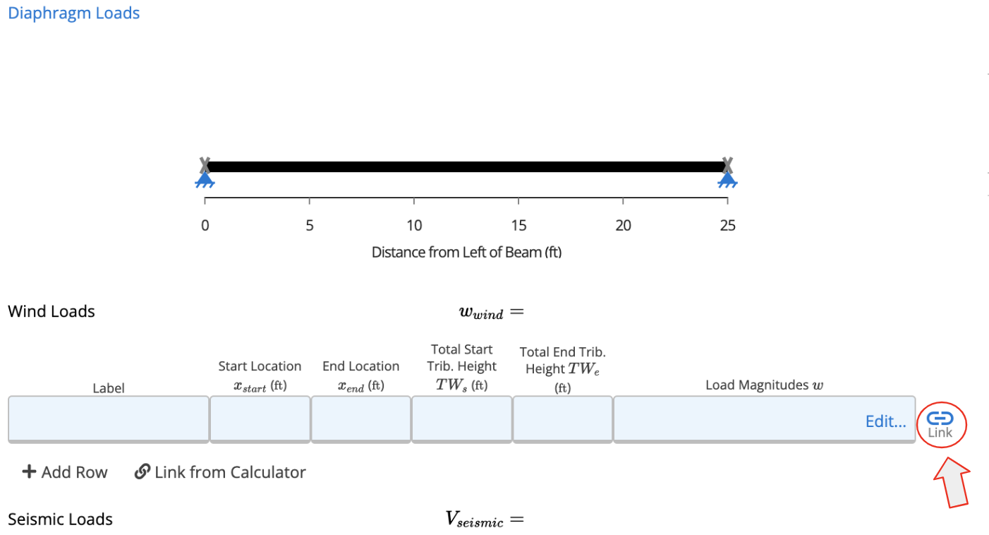
In the Diaphragm Analysis (Load Linking) calculator, you can link the wind loads to analyze and obtain essential results such as the reactions, shear diagram, shear demand in the diaphragm, and the governing load for shear in the diaphragm.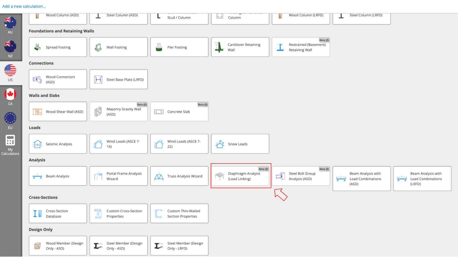 You can start by clicking the “Link” option, as illustrated in the following image:
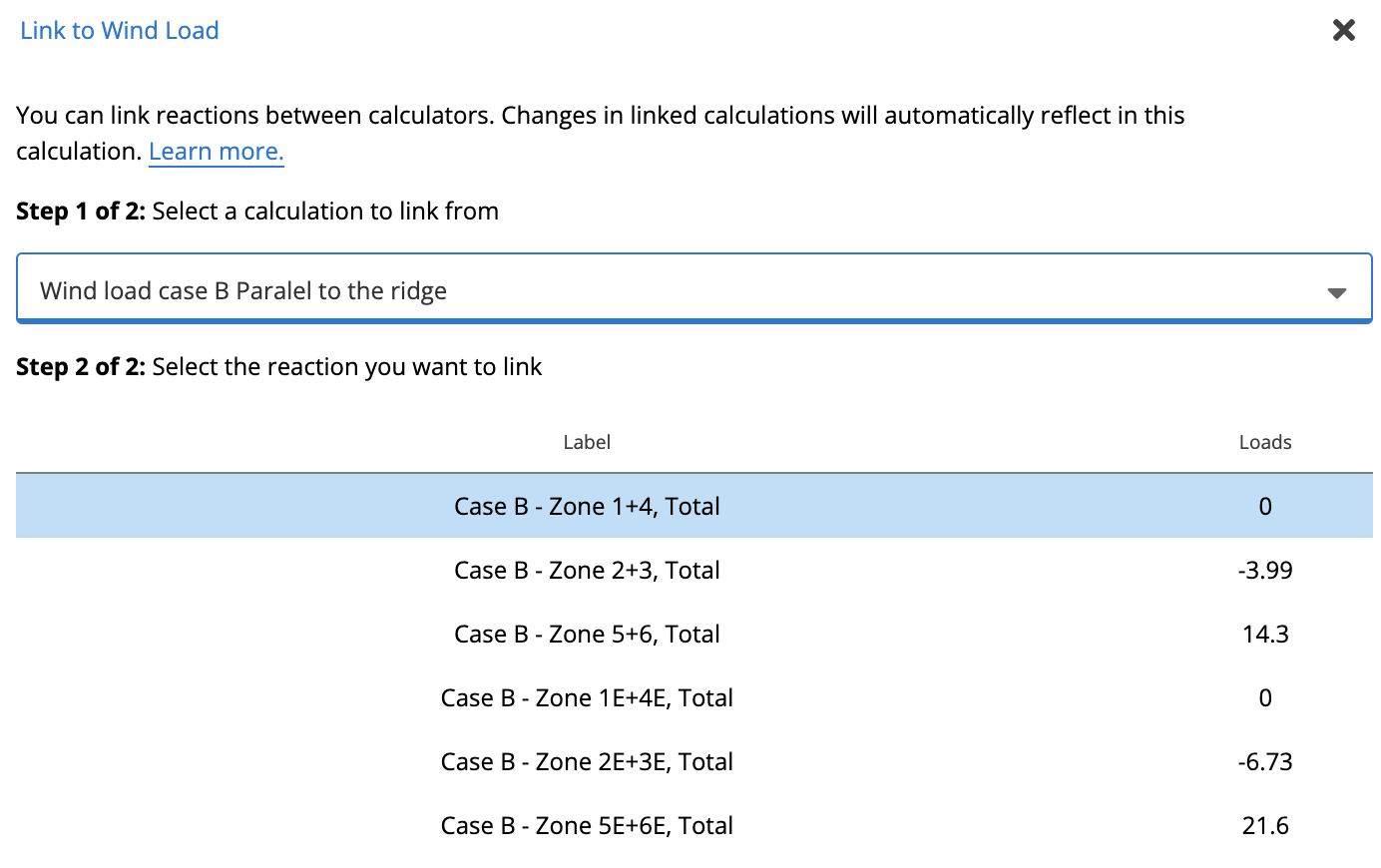
 Once inside, you can select the wind loads. Let’s start by linking the Wind loads Case B.To analyze the wind loads parallel to the ridge, zones 5-6 and the corner zones 5E and 6E will be the affected areas. You can input these zones into the calculator.
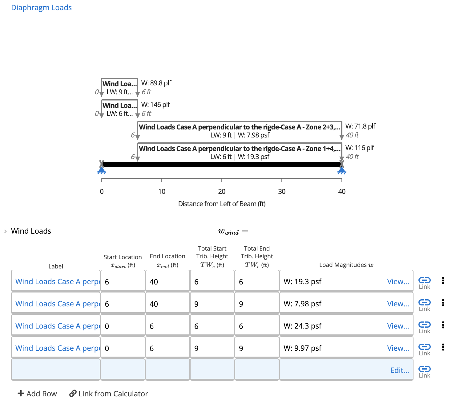
 Now that you have selected the wind loads, you can define the Start and End Locations along with the Total Start Tributary Height and Total End Tributary Height for each load. The following images provide detailed specifications for these parameters, including those specifically corresponding to the corner zones.
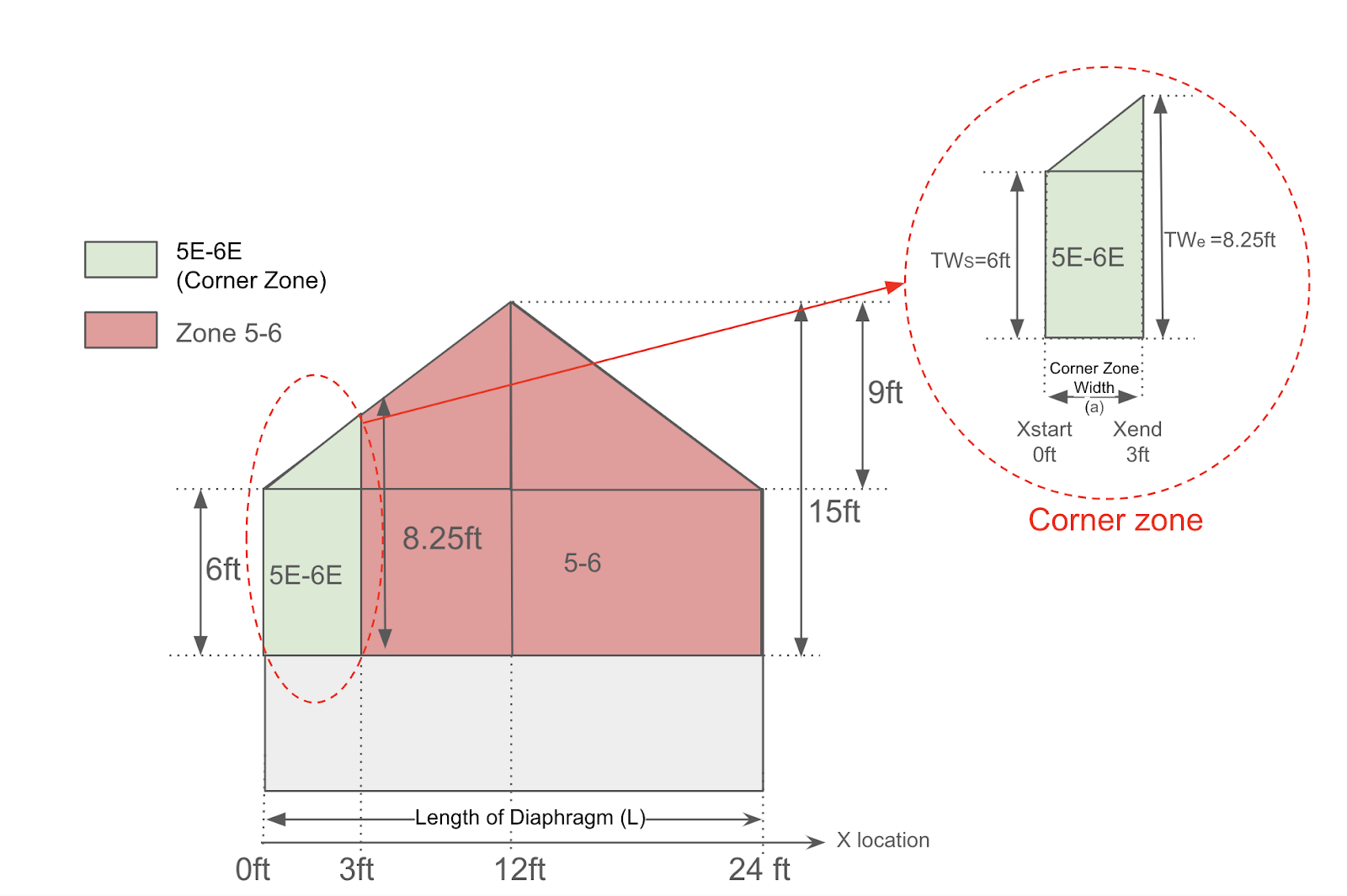
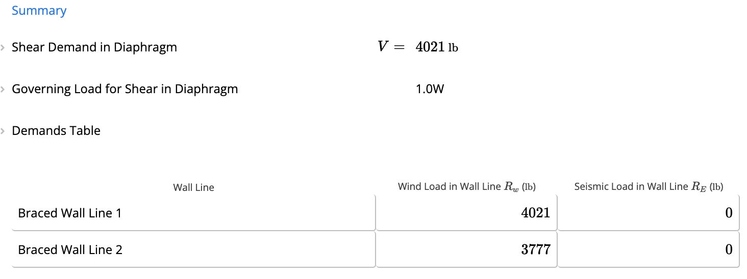
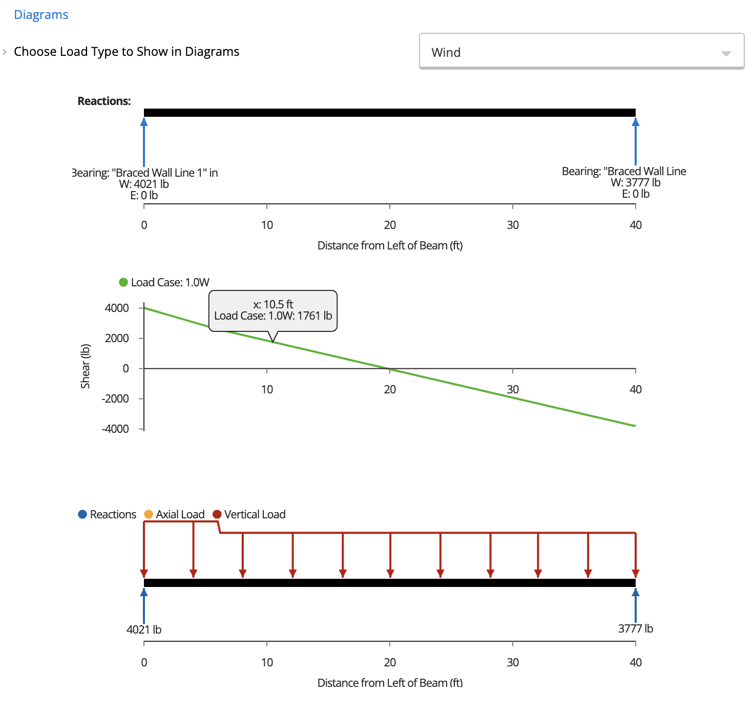
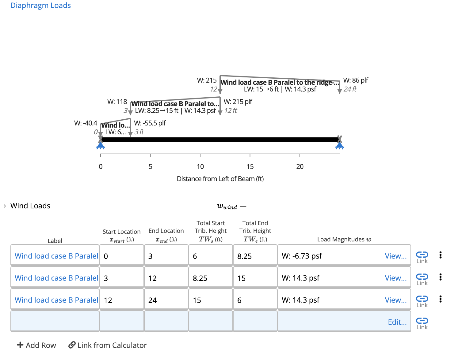 After the loads are entered into the table, you can review the results in the Summary Section and view the corresponding diagrams of your diaphragm.
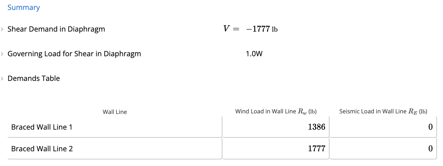
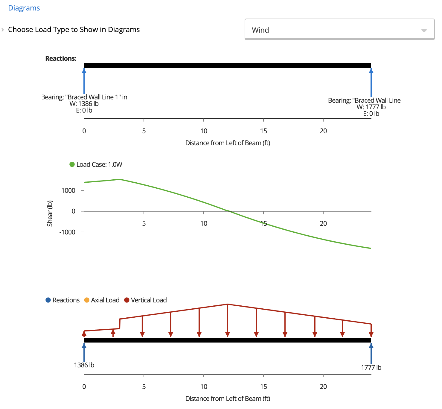 Similar to the previous procedure, you can use the same parameters for Wind Load Case B, applying them to zones 1-4, 2-3, as well as the corner zones 1E-4E and 2E-3E.