Follow along below or with this video:
Starting a Beam Calculation
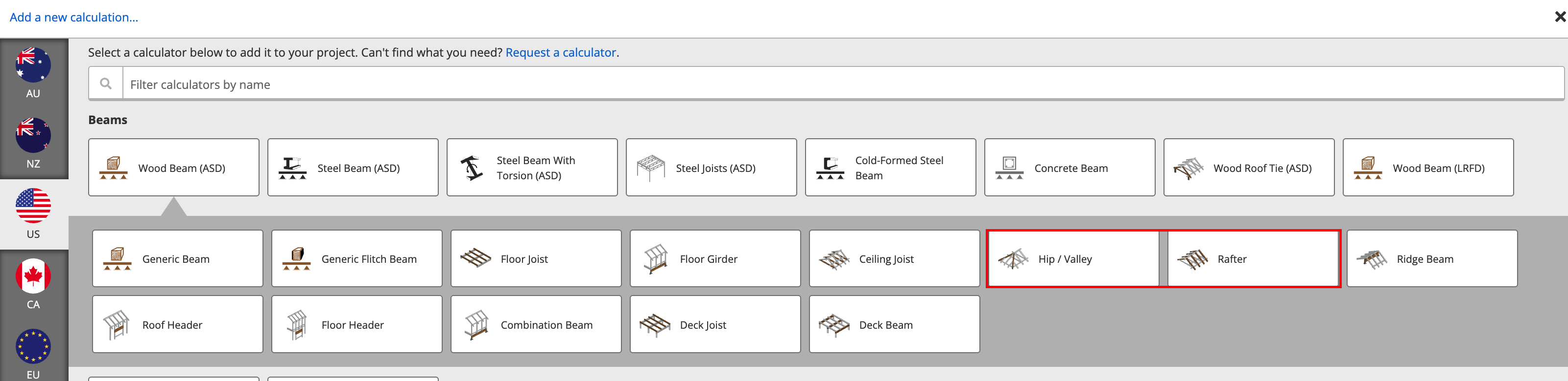
If you’re designing a beam, Calcs.com includes several presets specifically for roof elements, including the Hip/Valley Beam or Rafter. These presets automatically apply an incline.However, you can also start with a Generic Beam and define your own slope.
Setting the Beam Incline
In any beam calculation, you can set a sloped condition that allows you to input the incline pitch, as shown below. By default, a generic beam is assumed to have no slope, so we need to indicate this in our design conditions.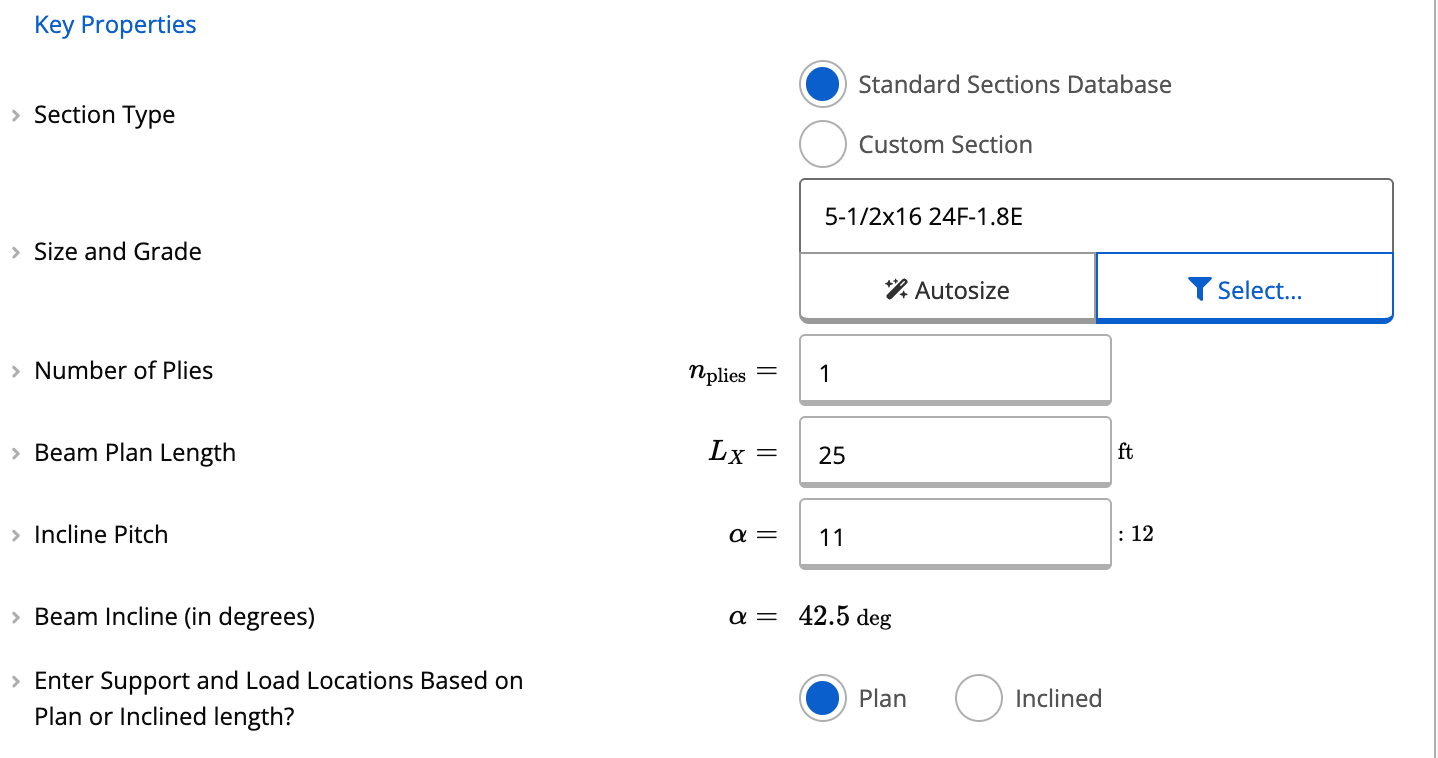
Where to Find Slope Settings
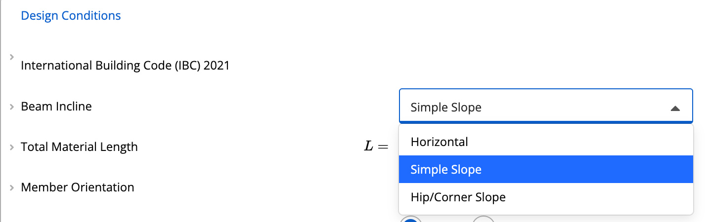
Scroll down to the Design Conditions section.Under Beam Incline Type, choose from:
- Simple Slope – defines a single plane incline (most common)
- Hip or Corner Slope – for beams sloping in two directions
Entering Your Slope
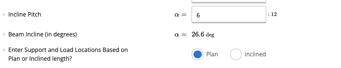
When Simple Slope is selected, additional inputs will appear allowing you to define the incline. You can enter slope in two ways:- Rise/Run (e.g., 11:12)
- The software automatically converts this to degrees
Choosing How to Enter Support and Load Locations
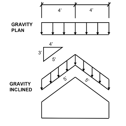
After defining the incline, choose how you want to input beam geometry and loads:- Plan View – distances measured horizontally based on the plan length
- Inclined View – distances measured along the slope of the beam
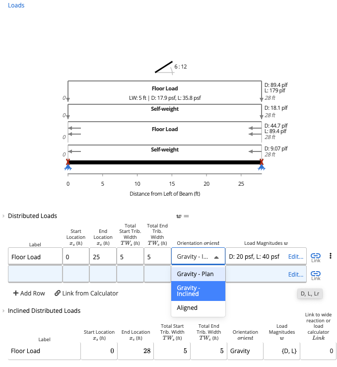
Defining Loads on the Inclined Beam
Calcs.com gives you flexibility in how loads are interpreted:- Gravity - Plan - loads applied over the plan length, meaning the horizontal projection of the structure
- Gravity - Incline - loads applied over the inclined length, meaning the actual sloped length of the structure
- Beam-Aligned Loads - applied directly along the sloped member
Linking Loads to the Beam
Once the beam is inclined:- Linked loads will automatically account for slope effects
- Reactions and internal forces are calculated using the true geometry