Background
A Flitch Beam is a composite section comprised of one or more steel plates attached to a wood beam. They are typically used to reduce the structural depth of an equivalent wood-only beam. To account for the differing stiffnesses and yield strength of the steel plate, the plate width is multiplied by a modular ratio n given by the below equation: n = Es⁄Ew The beam is now analysed with the transformed steel plate width (an equivalent wider wood beam) for section property checks. The Wood Beam ASD and Wood Beam LRFD calculators allow for calculating one or more steel flinch plates acting compositely with any wood section available in the database or via custom input. Calcs.com limits mounting plates parallel to the direction of the Primary Load for horizontal beams (as shown below): How to Use:STEP 1:
Select Yes to add flitch plates to the section
STEP 2:
Select the number of flitch plates to be added. For typical flitch plate configurations, we’ll also update our diagram to show you where the flitch plates are located. The location of the flitch plates don’t actually affect the calculations - they’re only shown on the diagram for clarity.
STEP 3:
Enter the dimensions of the flitch plates. These values are applied equally to each flinch plate. Plates are vertically centered to the wood beam centroid.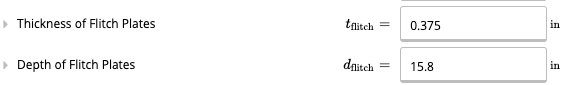
STEP 4:
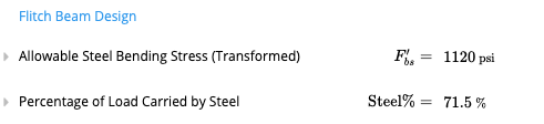
Enter the yield strength of the flitch plates. In general, A36 steel (Fy = 36 ksi) is used for flitch plates, although 50 ksi steel is also common. The Young’s Modulus of steel () is automatically set at . Review the Flitch Beam Allowable Steel Bending Stress, which is automatically used to determine capacity. By default, we show you the allowable stress based on the transformed cross-section, taking into account the modular ratio between the wood and steel elasticity.
Connection Design
The designer should also consider the connectors between the flitch plates and the wood beam. Calcs.com does not cover this detailing, however you may utilise Calcs.com to provide the necessary loading data on the flitch beam, by hovering over the “Loading Diagram” as shown below.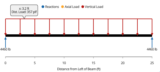 Where the joists (members spanning into the beam) frame into the side at regular spacing, you may design for the connectors to handle a proportion of the above load as shear perpendicular to the grain of the wood beam.
References
- NATIONAL DESIGN SPECIFICATION FOR WOOD CONSTRUCTION (2015)