Background Information
This example will look at the design of a concrete masonry wall cantilever retaining wall. We will design a reinforced concrete masonry cantilever wall that retains a level earth bank 9 ft above the final earth level and will check the utilization for bending and shear. This example is from the McGraw Hill Textbook, Design of Reinforced Masonry Structures, and can be found on Access Engineering.Given Data

Entering Your Properties
Under the key dimensions tab, we can design the geometry of the retaining wall. Starting with our wall type, this can be changed to CMU and the block width can be changed to 10”. Our wall height can be inputted as 9 ft. From the given diagram, the length of the toe can be calculated in Calcs.com. We can type in “6 ft + 9 in - 4 ft - 3 in - t_stem” to account for the total length of the base, less the length of the heel and the stem thickness, which will be calculated as 1.7 ft. The length of the heel can be entered as “4ft+3in” to result in 4.25 ft. The height of the backfill was given as 8 ft, and therefore the thickness of the footing is 1 ft.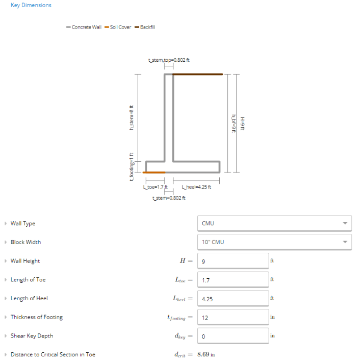
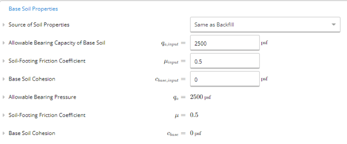
Soil Properties
Next, we have the soil properties that were given in the design example. The height of the backfill is set to “H” by default, corresponding to the total height of the retaining wall. The depth of soil cover to the bottom of the footing is located at 0 ft to correspond with the edge of the footing. The lateral pressure method used will be the Custom Equivalent Fluid Pressure so that we can input the given soil unit weight, active soil pressure, and allowable passive/lateral bearing pressure.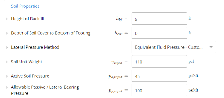
Masonry, Concrete and Reinforcement Properties
The masonry property for the specified compressive strength was given as 1800 psi. The self-weight of the concrete masonry wall was assumed to be a typical weight of 104 psf corresponding to a solid grouted, normal weight CMU. The concrete strength can be taken as the typical lower bound of 2500 psi, and our reinforcement was given as Grade 60.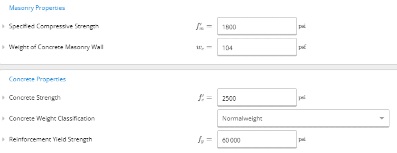
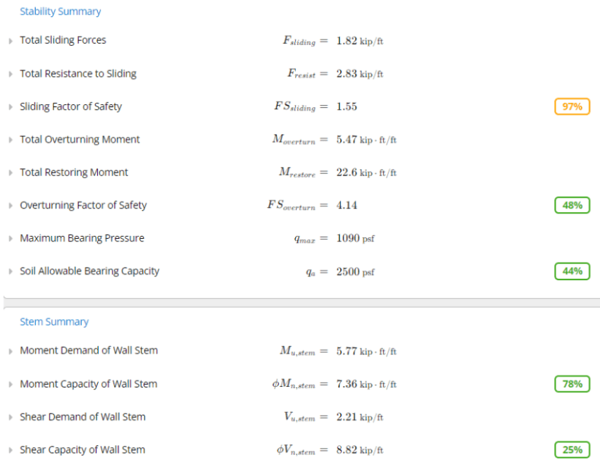
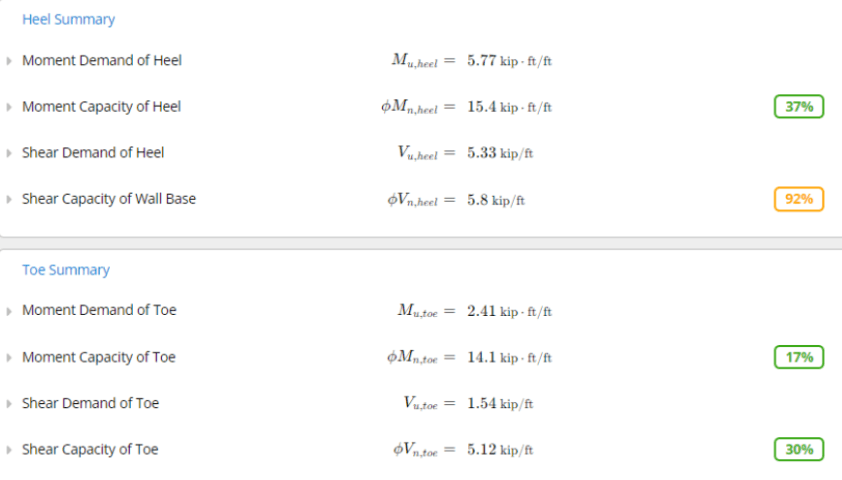
Summary of Results
Now that we have designed our cantilever retaining wall, we can look at the summary and see if our design passes (utilization below 100%). At the top of the page, we can see sliding forces, overturning moment and bearing pressure is calculated and checked against the minimum factor of safety. Below that, we have moment and shear demand and capacity utilizations being calculated. We can see that the factor of safety is greater than 1.5, which is generally a good minimum for design. We can also see that the moment and shear capacities have low utilizations. Overall, the retaining wall is governed by the sliding factor of safety at 97% utilization, with the minimum value being 1.5, and the determined sliding factor as 1.55.