Background
The Calcs.com Cantilever Retaining Wall calculator allows you to quickly design custom retaining walls according to IBC 2021. The calculator has presets available for fully drained conditions, high water tables, battered faces or L-type retaining walls. The calculator checks overall stability for sliding forces, overturning and restoring moment, as well as soil bearing pressure. The moment and shear utilization is calculated for the stem, heel, and shear key of the retaining wall. This calculator also allows for Rankine, Coulomb, or Equivalent Fluid Pressure methods to be used.Key Dimensions
Under the Key Dimensions section, the geometry of the retaining wall can be set. You can specify whether it is a concrete wall, or a CMU wall. For a concrete retaining wall with a triangular wall stem, you can enter a larger thickness at the base. Additionally, a rectangular shear key can be added with the same depth as the wall stem at the base.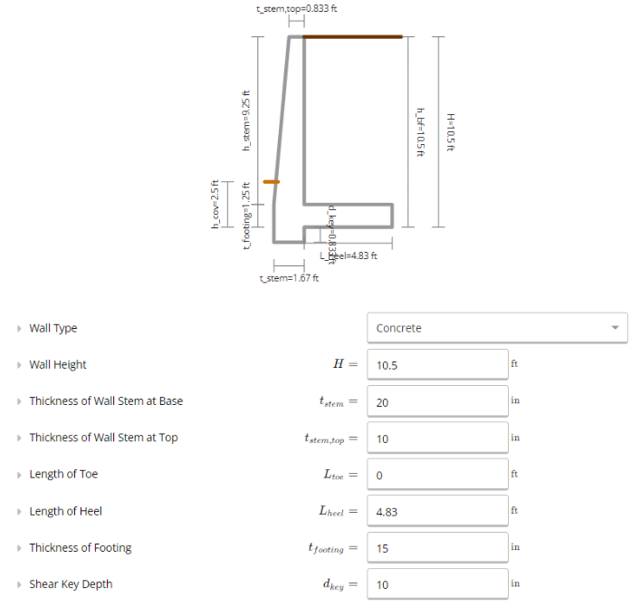
Surcharge
These properties can be defined if you have an additional dead load on top of the backfill. This may be a concrete slab, or another structure. This load typically increases horizontal loads, and therefore will reduce overturning and factors of safety. If you know your design will have the dead load directly over the heel, you can specify that in Calcs.com, in which case the dead load will help resist overturning and sliding. Similar to the dead load surcharge, the live load surcharge is applied to the backfill. It’s often taken as 100 psf for regular usage, or 250 psf for vehicular traffic. Calcs.com assumes that live load surcharge does NOT help resist sliding in overturning.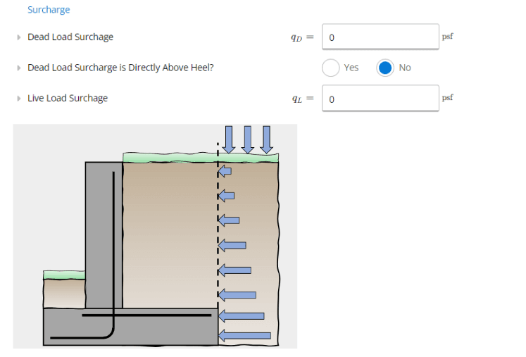
Seismic Loads
This input considers lateral loads due to seismic conditions. It will be considered in conjunction with other lateral loads and assumes a triangular distribution across the retaining wall. The lateral pressure from seismic loads are typically provided by a geotechnical engineer or report. This value should be entered at the strength (LRFD) level, as it will be factored later in the calculations.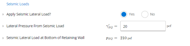
Soil Properties
Here you can specify the properties of the soil, both for the backfill and base soil. You can also define which lateral pressure method will be used. Calcs.com supports Equivalent Fluid Pressure, Rankine and Coulomb methods. The equivalent fluid pressure considers a simplified earth pressure applied on the wall, for ease of calculation. Rankine’s earth pressure, where the soil’s internal friction angle is considered. This method assumes the failure surface is planar, the soil is cohesionless, the wall is non-battered and frictionless, and that the backfill is horizontal. Lastly, Coulomb’s earth pressure considers the failing soil block as a free body and can be used to account for wall friction. Rankine and Coulomb methods are often used since they are more theory-based and versatile.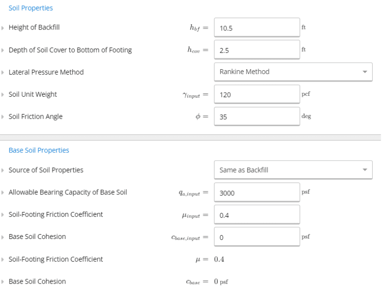
Concrete Properties
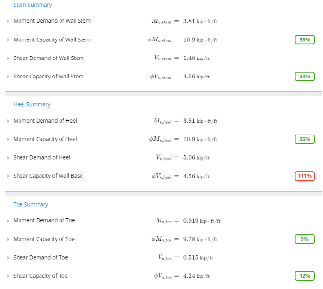
The next few sections in the calculator let you design the concrete and reinforcement for your retaining wall. For this calculator, the concrete detailing needs to be checked separately. Our calculations will only be used to determine if the moment and shear capacity of the stem, and heel are adequate. The inputs for reinforcement are checked against ACI 318-19. Shrinkage/temperature reinforcement can also be specified as a single row of reinforcement bars running perpendicular to the wall direction. As the reinforcement properties are updated, the depth and spacing is checked against ACI 318-19 at real-time. These values are compared to the minimum steel area required, as well as the estimated maximum spacing, assuming an under-reinforced section. This is checked in the heel, toe and stem of the retaining wall.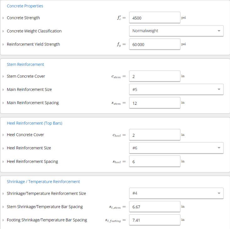
Calculations and Results
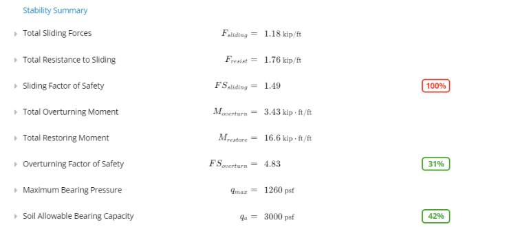
Once all of the soil and wall properties have been inputted, we can look at our calculations and results. For retaining walls, we can expect four common modes of failure. This could be sliding, overturning, footing bearing failure, or concrete failure. At the top, in our stability summary, we can see the total sliding forces and resistance to sliding. The sliding forces consist of the lateral pressure loads and surcharge. The resistance to sliding considers the soil friction coefficient and total vertical loads. The factor of safety should generally be above 1.5 however this value is compared against the minimum factor of safety. If it is overutilized, the design will result in sliding failures. One way to overcome this could be to widen the heel, or to add a shear key. The overturning moment, and restoring moment used to counteract these forces are calculated below that. The overturning moment is calculated from the lateral soil loads and surcharge, while the restoring moment is taken about the toe of the entire wall. It considers its self-weight and the soil above the heel. Overturning failures can occur here if the factor of safety is less than the minimum required. This can be resolved by widening the retaining wall footing. The maximum bearing pressure is also calculated at the toe of the retaining wall. It is compared against the soil allowable bearing capacity, which is often provided by local code or a geotechnical report.