

 | Anywhere you see the chain link icon, you can click to link a load (reaction) from another calculator in your project. |
Linking Wall Loads to Beams / Lintels
Are you designing a beam supporting a masonry wall? Do you need to take into account windows or other openings? This can be accomplished through the Calcs.com linking functionality.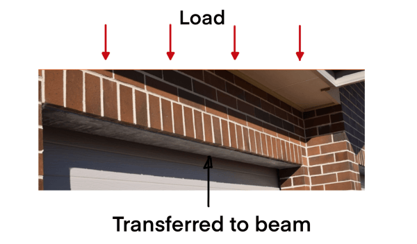
STEPS*:***
- Create a Wall analysis calculation, and apply your loads.
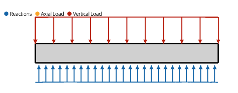
- The reaction arrows marked in blue are the reactions that will be linked to your beam.
- Create a “steel beam” or “wood beam” calculator, and click the link icon under “Line Loads”
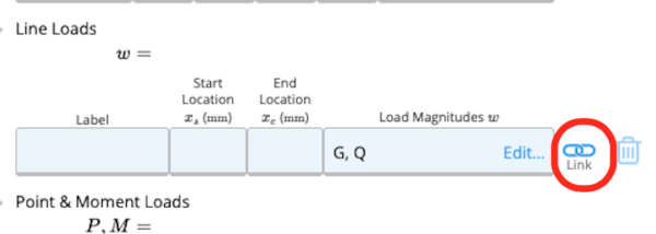
- Then select the wall reaction.
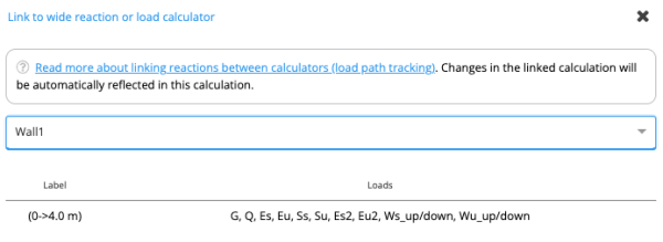
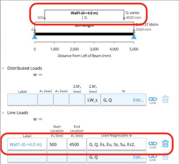
- Enter a start and end position. For example, I have a 5m beam below, and the wall is 4m long, so I have centered it to the beam.
Linking Distributed Rafter / Joist Loads
Did you know that rafters or joists may be linked into a bearer as a line load? This would be useful in the case where regularly spaced beams each will have the same reaction. This may be visualised to the diagram of a floor joist below: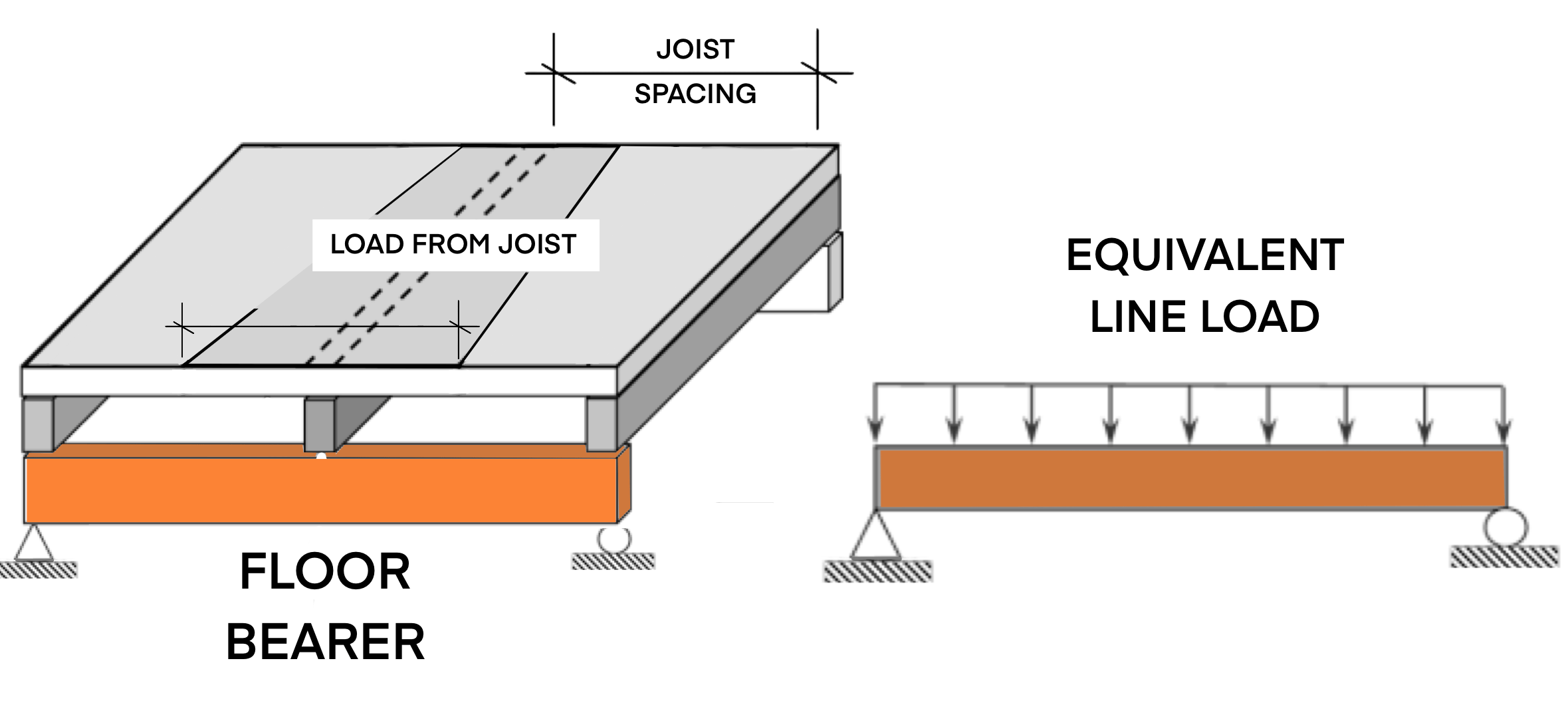
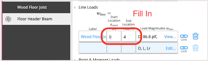
To do this, enter the joist spacing as shown below:
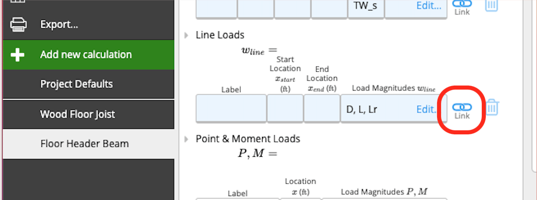
 Then in your header beam, link the Floor Joist as a “Line Load”:
- If you make changes to a beam which is linked and bearing onto others, make sure to check those sheets to ensure they are still passing (you can see their status in the sidebar or member schedule)
- Calcs.com will automatically detect and stop circular references, but it will not allow you to delete beams that are linked to each other. You will be warned that other sheets are linked to this before you delete, and if you proceed you’ll need to go to those sheets and clear the link/point load.
Sign convention for linked reactions
Calcs.com uses separate sign conventions for loads and reactions. Positive loads act downward (gravity direction); positive support reactions act upward. These conventions coexist and do not contradict each other. See Sign and Axis Conventions. The value passed through a load link is the upstream calculator’s vertical support reaction, taken exactly as it appears in that calculator’s reaction table. For typical gravity loading at a support, positive values are upward. No sign flip is applied at the point of linking, regardless of the relative vertical position of the two calculators. A column sitting below a beam receives the same value, with the same sign, as a hanger picking up that beam from above. If you need the load to act in the opposite sense in the downstream calculator, you’ll need to handle that explicitly, either by reading the reaction table directly or by applying the load manually.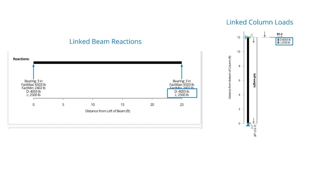
How factoring works across linked loads
Linked loads pass between calculators at ultimate (unfactored) values, per load type (D, L, S, W, E, etc.). Each receiving calculator then applies its own load combination factors once, internally — for example, an ASD shear wall will apply the 0.7E factor when it forms combinations, but a diaphragm sitting between two walls does not re-factor the seismic value on the way through. This means an “ultimate” input label upstream and a “factored” output label downstream can look different without indicating any double-factoring. It is the single, correct application of the load combination factor. For a multi-story lateral load path (wind or seismic → diaphragm → shear wall → wall below), link each shear wall from its own floor’s diaphragm rather than chaining a shear wall reaction directly into the wall below.Load direction for inclined members
When linking a reaction into a downstream member that sits at an angle (for example, an inclined rafter feeding into a column), the “Load Direction When Linking” setting controls the axis along which the reaction is applied to the receiving member. Choose the axis that matches how the downstream member is actually resisting the load — global vertical/horizontal, or local (perpendicular to the member). Typical gravity beam → column links pass force reactions (axial and shear). Do not rely on linking for moment continuity between calculators — if fixed-end moment transfer matters to your design, enter or check those moments explicitly rather than assuming the standard load link carries them.Why linked values may differ from the raw reaction
When you link the reaction from a repeating member (e.g. joists at a fixed spacing) into a supporting beam, Calcs.com converts the per-joist point load reaction into an equivalent line load based on the assumed tributary spacing before applying it to the downstream member. That is why the linked line load value on the beam will not numerically match the point load reaction reported by the joist calculator — it is the same load, expressed over the tributary width.Finding a reaction when the calculator has no reactions table
Some member calculators (for example, the Wood Column calculator) don’t expose a dedicated reactions table. In those cases the reaction is computed internally and only exposed via load linking into the member below. To view the value directly, check Critical Axial Load in the Summary or read the Axial Force diagram at the base of the member.Which calculator pairs support load linking
Load Path Tracking works only between specific calculator pairs. If you don’t see a chain-link icon on the load or reaction you’re trying to link, that pair isn’t currently supported — and no amount of retrying or reordering the sheets will surface one. The most common supported chain is stud walls linking via the Wood Column or Wood Beam calculators: reactions at each stud pass into a Wood Column, and beam reactions pass into a Wood Beam sitting below. Rafter and joist reactions also link into supporting Wood Beams as either point loads or an equivalent line load, as shown earlier in this article. Masonry Gravity Wall does not currently link into Wall Footing. If you’re designing a masonry gravity wall bearing onto a wall footing, the base reactions from the Masonry Gravity Wall sheet will not appear as a link option inside the Wall Footing input table. This one has caught users out — treat it as a manual transfer.Workaround when a pair isn’t supported
Copy the reactions across manually, keeping each load type separate:- Open the upstream calculator (e.g. Masonry Gravity Wall) and find the reaction table. The base reactions are reported at ultimate (unfactored) values, broken down by load type — dead (D), live (L), snow (S), wind (W), seismic (E), etc.
- In the downstream calculator (e.g. Wall Footing), enter each reaction into the load input table under its matching load type. Do not sum load types together — the receiving calculator applies its own load combination factors internally, and combining upstream will double-count or misapply factors.
- Re-check the input each time you change something in the upstream sheet. Manual transfers do not update automatically.