


Worked example
Example 1: single-span column with lateral loads
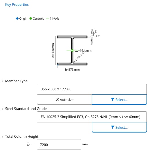
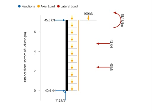
A steel column is 7200 mm high, pinned at the base and on a roller at the top. It carries an axial load at the top and two lateral point loads, and it is braced against lateral movement at the lateral loads. The steps below use the conditions in the image. The design criteria in step 6 are the example’s own settings, not the calculator’s defaults.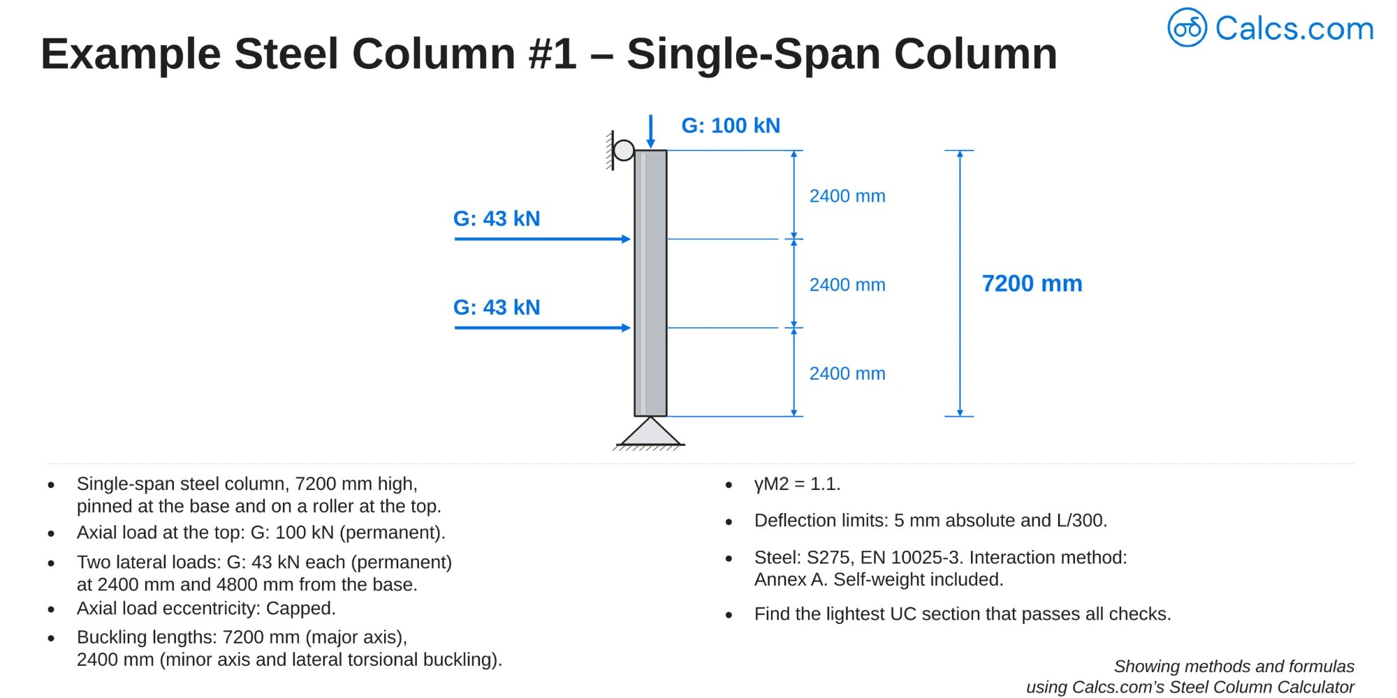
- Single-span steel column, 7200 mm high, pinned at the base and on a roller at the top
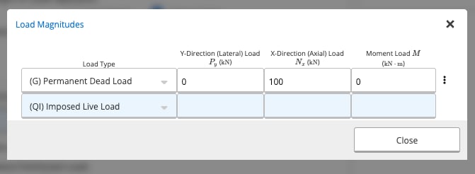
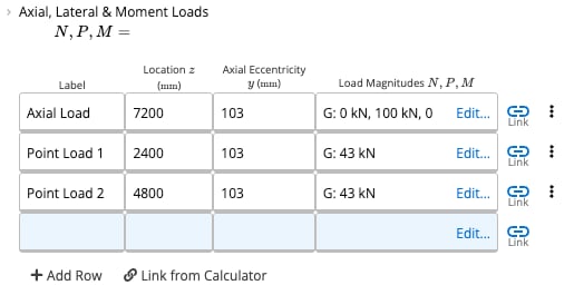
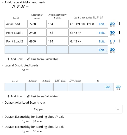
- Axial load at the top: G of 100 kN (permanent)
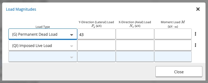
- Two lateral loads: G of 43 kN each (permanent) at 2400 mm and 4800 mm from the base
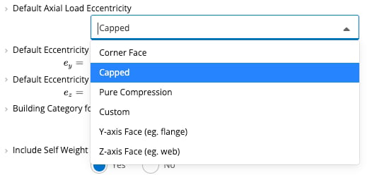
- Axial load eccentricity: Capped
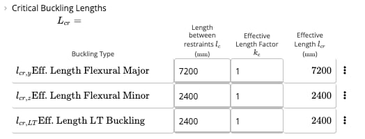
- Buckling lengths: 7200 mm (major axis), 2400 mm (minor axis and lateral torsional buckling)
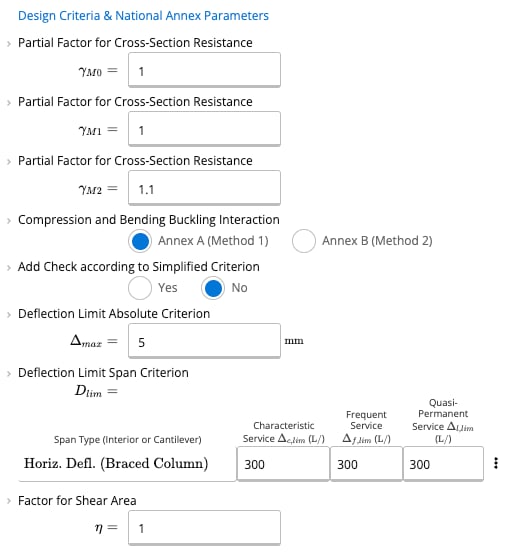
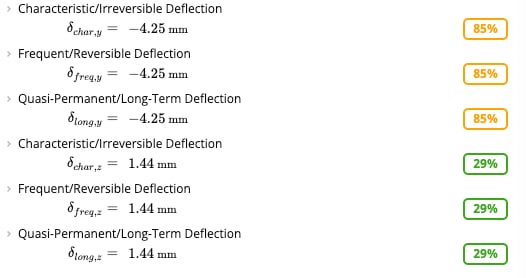
- of 1.1, and deflection limits of 5 mm absolute and L/300
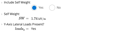
- Steel S275 to EN 10025-3, interaction method Annex A, self-weight included
- Find the lightest UC section that passes all checks
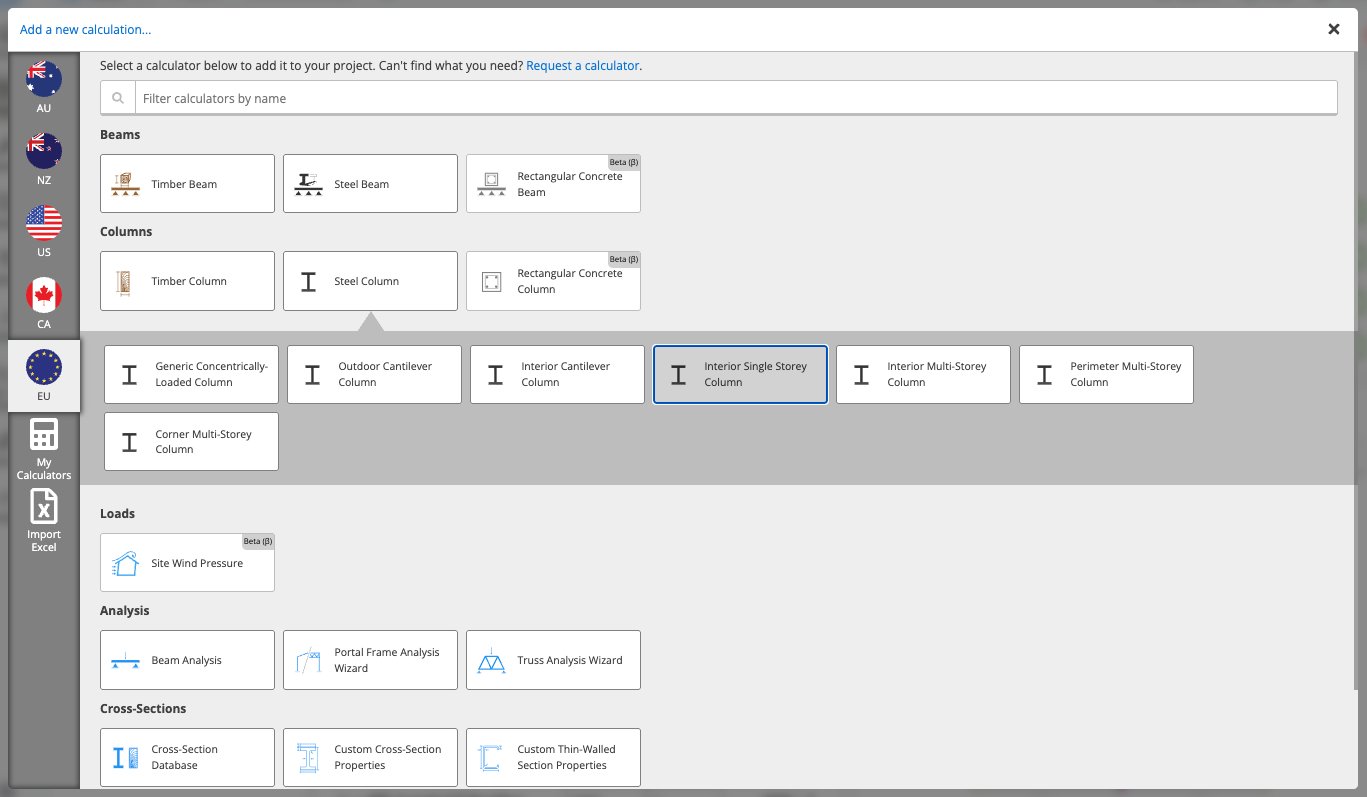
Add the Steel Column calculator
Set the height and the buckling lengths
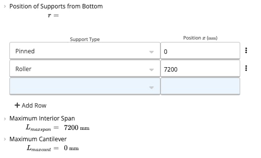
Place the supports
Enter the loads
Set the eccentricity
Set the design criteria
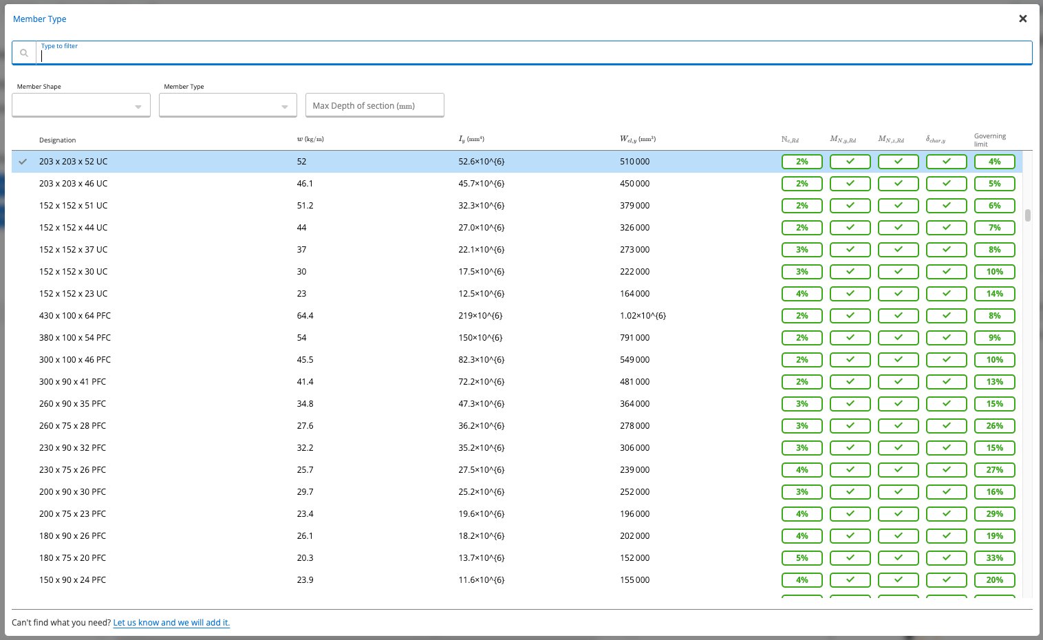
Choose the section

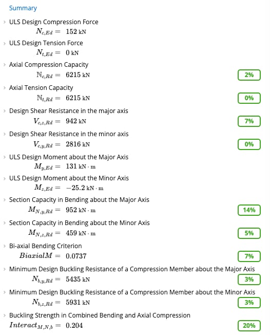
Read the summary

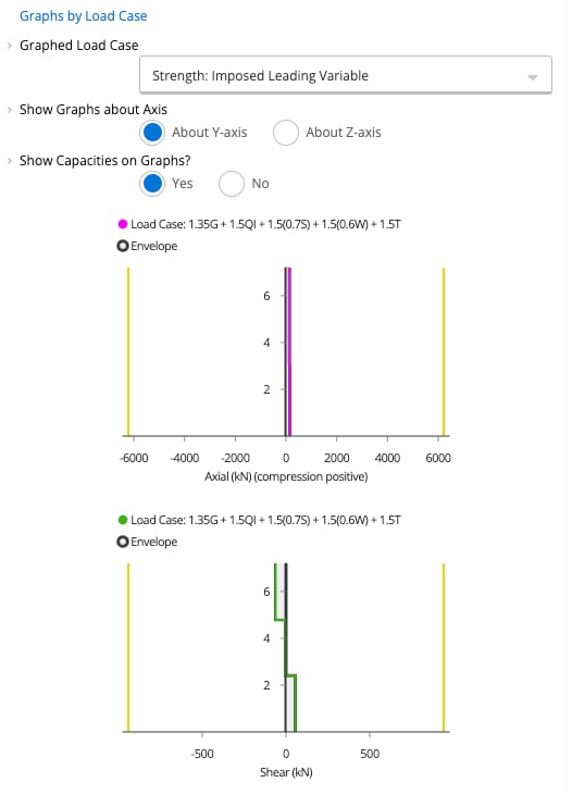
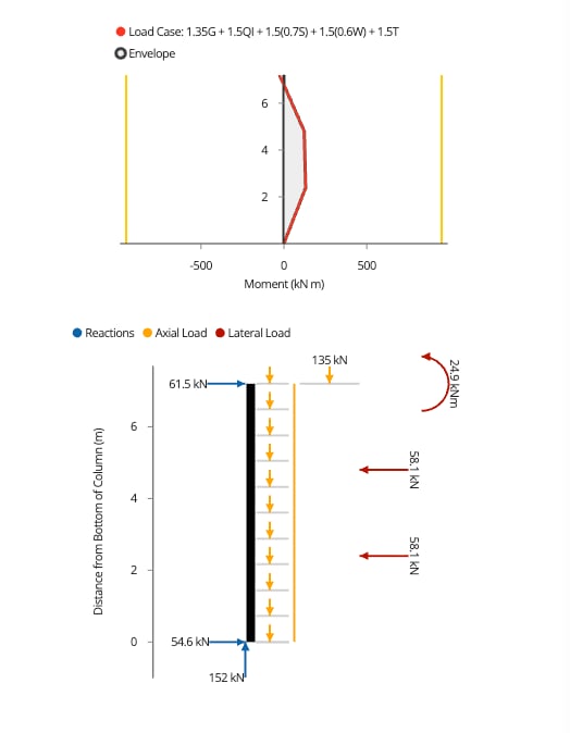
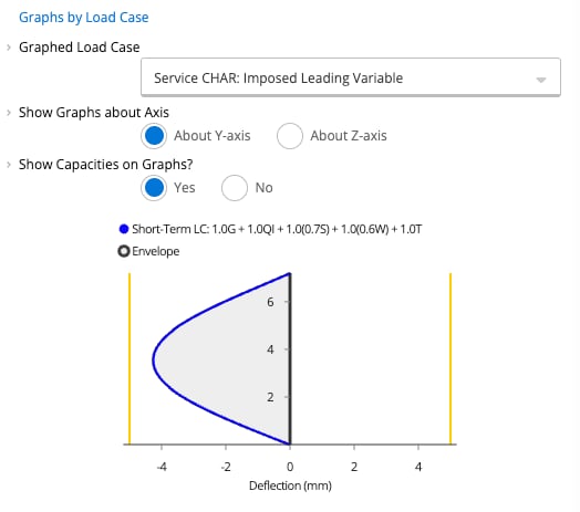
Look at the graphs
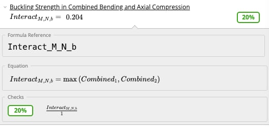
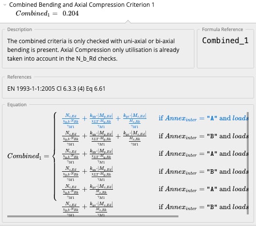
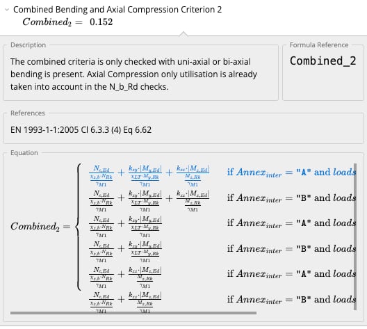
See how the combined check is worked out
Inputs
Calcs.com output
Hand check
The loads, reactions, major-axis design moment and deflection match the closed-form solution. The capacities, buckling and combined buckling checks, and the minor-axis moment are advanced results from the calculator, with no hand check. This is a sanity check only. Steel Column version 46, Interior Single Storey Column preset.
Method & scope
Analysis and design capabilities
The EU steel column calculator can be used to calculate both the demands as well as the resistance of a straight column.The analysis capabilities include:
- Point Axial and lateral forces
- Point moments in the major and minor axis (excluding torsion)
- Line Loads (including linearly varying)
- Distributed Loads (including varying tributary width). For details on tributary widths, refer article Understand Tributary Width
- Cross-section classification (Class 4 section design not available)
- ULS: Axial compression and tension resistance (EN 1993-1-1:2005 Cl 6.2.3 & 4)
- ULS: Reduced bi-axial moment resistance taking into account axial and shear forces (EN 1993-1-1:2005 Cl 6.2.5)
- ULS: Shear resistance (EN 1993-1-1:2005 Cl 6.2.6)
- ULS: Lateral torsional buckling resistance of uniform member in bending (EN 1993-1-1:2005 Cl 6.3.2)
- ULS: Buckling resistance in combined bending and axial compression (EN 1993-1-1:2005 Cl 6.3.3)
- ULS: Flexural buckling resistance in axial compression (EN 1993-1-1:2005 Cl 6.3.1)
- ULS: Shear web buckling resistance of uniform member (EN 1993-1-5:2006 Cl 5.1-5.5) including transverse stiffeners.
- SLS: Deflection analysis
- Penetrations or fastener holes (checks if they may be ignored)
Informational and National Annexes
Eurocode allows location-specific factors and/or calculation methods to be utilized. These are usually stipulated within National Annexes to EN1993-1-1:2005. The following customizations are provided within Calcs.com:- Partial Factors for cross-section resistance - The recommended values within EN1993-1-1:2005 Cl 6.1(1) are provided by default, however, modified values should be used specifically to the relevant National Annex.
- Interaction Factors for compression and bending buckling resistance - 2 methods are provided within the informational annexes. The engineer should consider both the national annex requirements as well as the validity of each method for the type of sections they are designing. The UK National Annex limits the scope of Annex A to bi-symmetrical sections; unless noted otherwise by your national annex, it is not recommended to use Annex A for PFC sections.
- Deflection Limits - These vary based on the type of the structure, whether it is a column or beam, as well as national annex preferences. Extension limits are not provided, however where differential deflections of multiple columns may induce secondary impacts, a separate check should be conducted. These may be adjusted within Project Defaults, which apply to all designs within the project, or amended for this column only.
Assumptions and Limitations
Calcs.com fully exposes all code calculations to see every step of the process employed to design the column. Therefore, the engineer should have confidence that they can look at every calculation and conditional statement that is used to derive the final result. A summary of assumptions is provided below:- Columns are computed by a chosen limit state and load combination. It is up to the user to choose limit states to determine the worst loading case combination. These may be viewed and/or modified in Project Defaults.
- Hollow sections are analyzed as cold-formed (more conservative than hot-finished) for the purposes of buckling checks
- Flexural torsional buckling (Cl 6.3.1.4 EN1993.1.1:2005) is not checked as the database hot-rolled sections and hollow sections will always have more critical flexural buckling limits.
- Supports are equally applied about both axes (i.e. fixed in bending about major and minor axes)
References
The worked example above is based on Example 6.9, Gardner and Nethercot (2011), Designers’ Guide to EN 1993-1-1 (Eurocode 3).See the exact clause
Symbols
These are the labels the calculator shows in its inputs, Summary and tables.Calculation method
Structural model and load combinations
The calculator models the steel column as a member under combined axial force and biaxial bending. Loads are entered by type: permanent , imposed , snow , wind , temperature and earthquake . EN 1990:2002 governing ULS combinations are generated automatically. Bending moments can be entered directly or linked from beam calculations above. Three serviceability combinations generate deflection checks.Cross-section classification (EN 1993-1-1:2005 Cl 5.5.2)
Cross-section class (Class 1 through 4) is determined independently for major-axis bending, minor-axis bending, and axial compression based on element slenderness and . The governing class controls which section moduli (plastic, elastic, or effective) are used in the resistance calculations.Cross-section resistance
Axial compression (Cl 6.2.4): for Class 1-3, or for Class 4. Bending (Cl 6.2.5): uses for Class 1-2, for Class 3, and for Class 4, independently for both axes. Shear (Cl 6.2.6): is computed from the shear area and yield strength for each axis. Biaxial bending criterion: For combined major and minor axis bending without axial force, the biaxial criterion limits the sum of moment utilization ratios. Simplified criterion (Cl 6.2.1 (7) Eq 6.2): As a conservative approximation, a linear summation of the utilization ratios for each stress resultant can be requested with Add Check according to Simplified Criterion. This may be applied for Classes 1 to 3.Flexural buckling resistance (EN 1993-1-1:2005 Cl 6.3.1)
Flexural buckling resistance is computed for each axis using the reduction factor , derived from the relative slenderness . is the Euler critical load based on the effective buckling length. The imperfection factor depends on the section type and axis (buckling curves , , , , per Table 6.2). buckling utilizationLateral torsional buckling (EN 1993-1-1:2005 Cl 6.3.2.1)
When the compression flange is not fully laterally restrained, LTB resistance is computed using from the relative slenderness derived from . The critical moment accounts for unbraced length, end conditions, and section warping and torsional properties.Combined bending and axial compression, member buckling (EN 1993-1-1:2005 Cl 6.3.3)
The combined buckling interaction is checked through two criteria, (EN 1993-1-1:2005 Cl 6.3.3 (4) Eq 6.61) and (Eq 6.62), using the interaction factors , , , : The sheet reports . It picks the terms by interaction method (Annex A or B) and by which axes carry loads, and makes the check only when uni-axial or bi-axial bending is present. Axial compression alone is covered by the checks. Interaction factors are derived from the moment distribution ( factors) and relative slendernesses.Deflection checks (EN 1990:2002 Cl 6.5.3)
Characteristic, frequent, and quasi-permanent deflections are checked against user-defined span-ratio limits and optional absolute limits in mm.Load linking
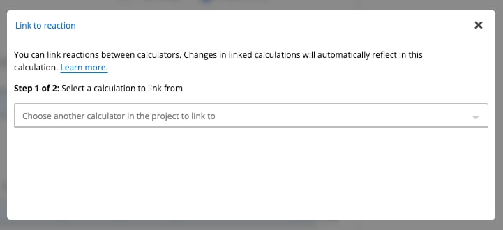
The column’s base reaction is exported as a linked output to connected footing calculations. Axial load at the column top can be linked from beam reactions above, completing the full load path from beam to column to footing automatically. When reactions are linked into a column, the reactions in both axes are shown, identified by X and Y next to the support number.How to use it
The sheet has Key Properties, Loads, Design Criteria and National Annex Parameters, and Penetrations or Fastener Holes, then the Summary and the graphs. The screenshots show a 203 x 203 x 52 UC column, 5000 mm high, fixed at the bottom and on a roller at the top.Add the Steel Column calculator
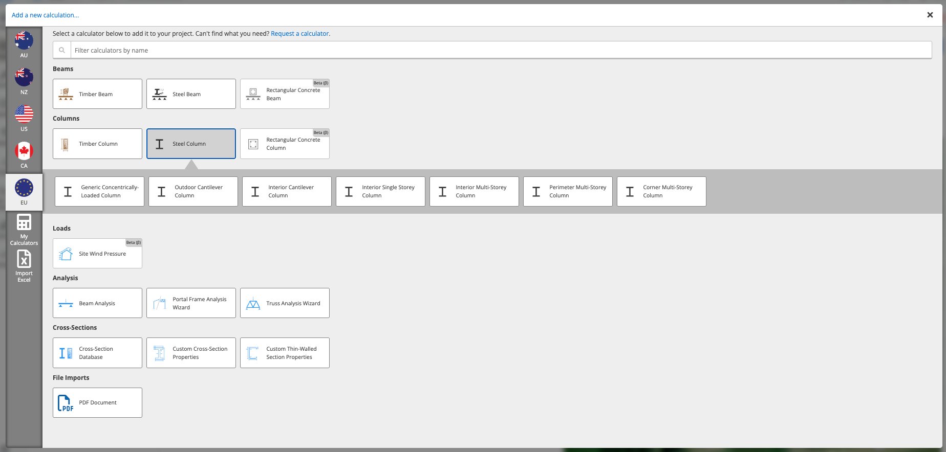
Choose the member and the steel grade
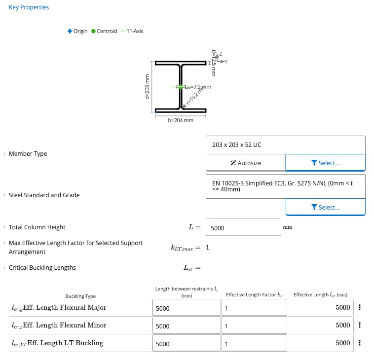
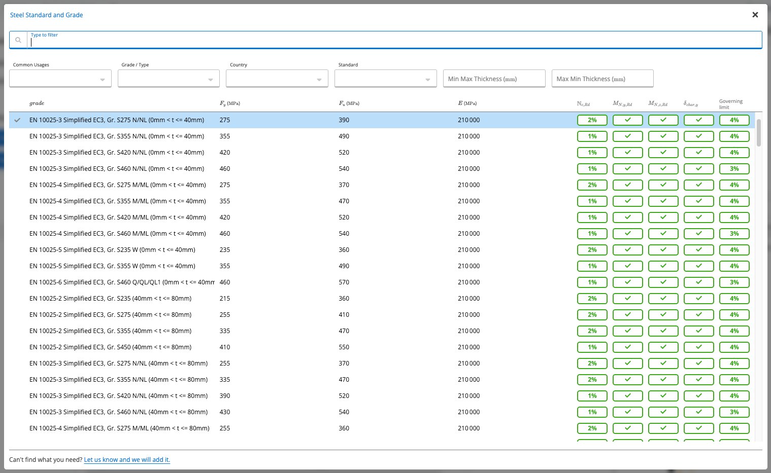
Set the column height and the buckling lengths
Place the supports
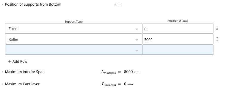
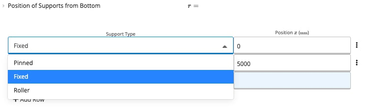
Enter the loads
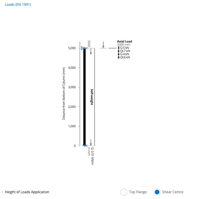
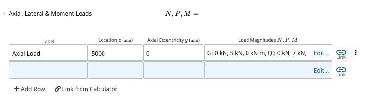
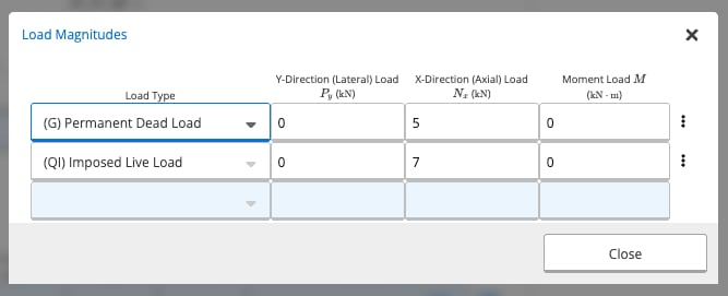


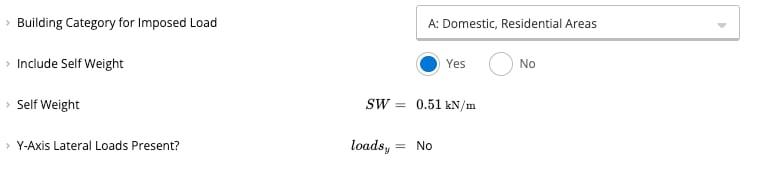
Choose the building category and the self-weight
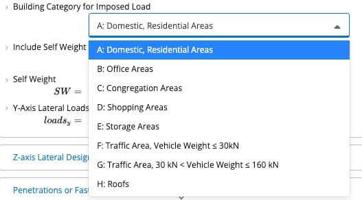
Set the design criteria
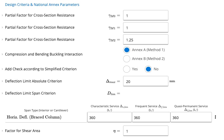
Add penetrations or fastener holes (optional)
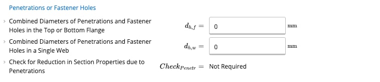
Read the results

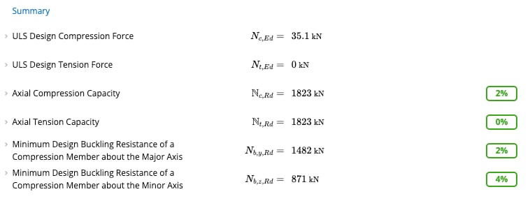
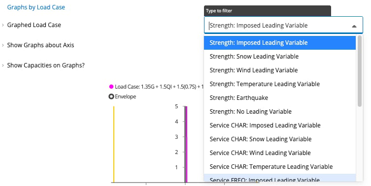
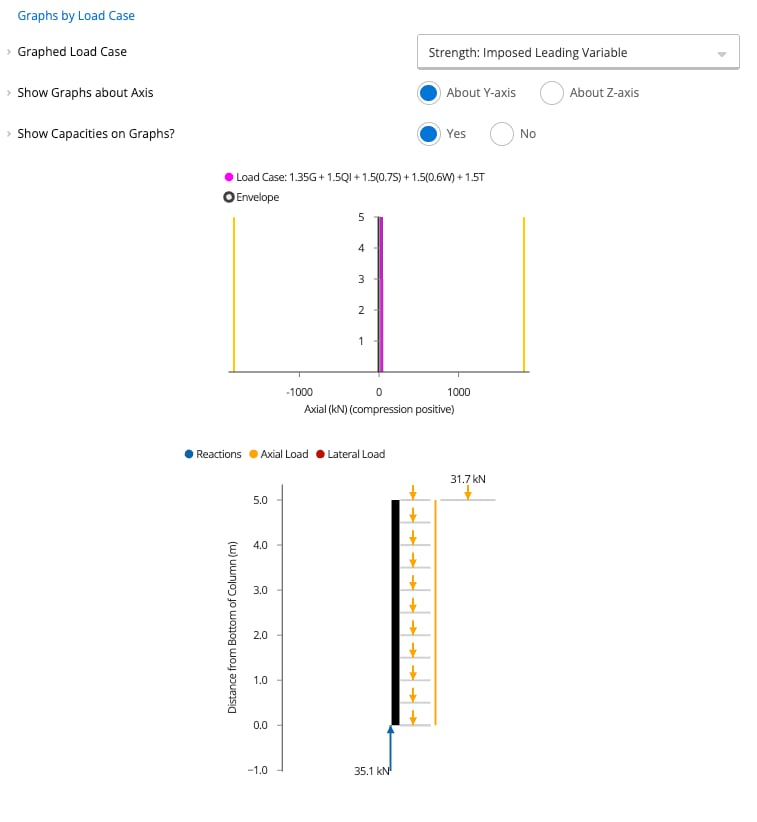
See how each check is worked out
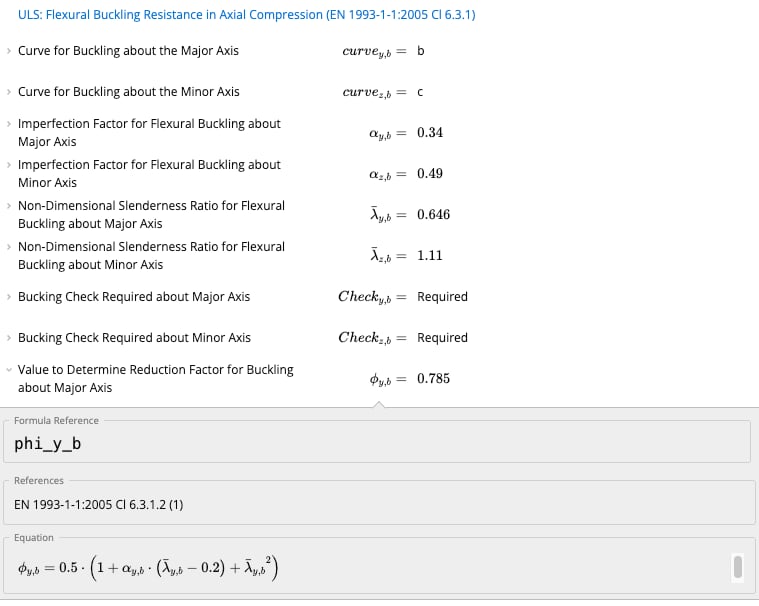
Available presets
Each preset opens the calculator with a typical setup already entered.Common questions
What design standard does this calculator use?
What design standard does this calculator use?
What are the key inputs?
What are the key inputs?
What checks and outputs does it produce?
What checks and outputs does it produce?
How are flexural buckling and LTB checks combined with axial compression?
How are flexural buckling and LTB checks combined with axial compression?
How is the cross-section class determined for biaxial bending?
How is the cross-section class determined for biaxial bending?
Does this calculator support load linking with beam and footing calculations?
Does this calculator support load linking with beam and footing calculations?