

1. Background
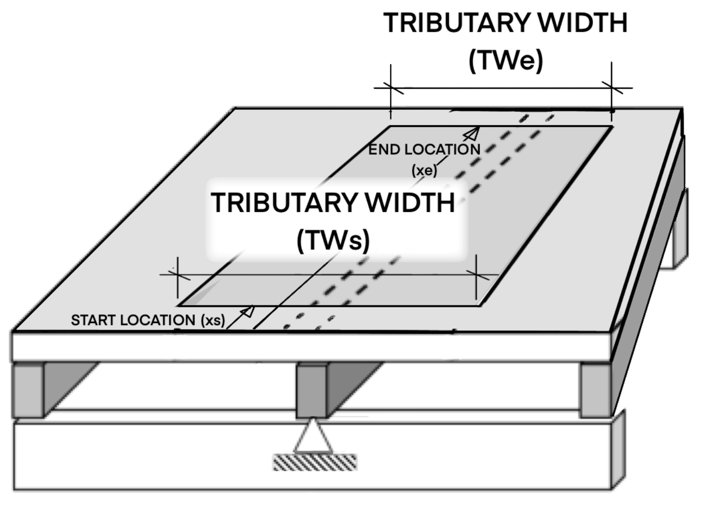
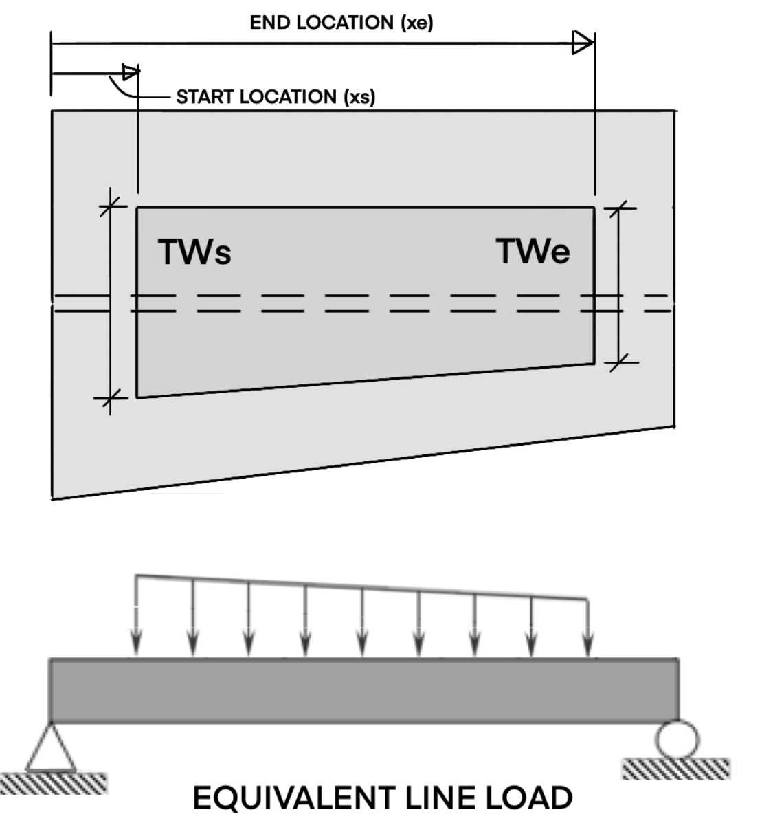
Applying loading via a distributed / tributary area is useful when designing floors, roofs or other beams supporting slabs. The vertical or gravity loads are usually distributed one-way between regularly spaced joists or rafters, as depicted in Figure 2 below. The load on a floor or a ceiling is distributed on the area of the structural element (force/area). The equivalent beam line load is equal to the “tributary width” multiplied by the “area load”. E.g. 3 m (TWs/TWe) * 2.5 kPa (G/Q area load).2. How to enter distributed loads in Calcs.com
Calcs.com provides an easy way to enter area loads by providing 4 dimensions and the area load.- Start Location (x_s) - area loading may start at any point along the beam (e.g. only applied on one span)
- End Location (x_e)
- Start Load Width (TW_s) - may be different than TW_e as shown in Figure 2
- End Load Width (TW_e)
- Load Magnitude / Area Load(w)

E.g. if a load “q” in KPa (kN/m²) is applied on a slab and the tributary width “TW” is in meters length, the line load will be obtained by q x TW (kN/m).
3. Worked Example
Given the structural arrangement in Figure 4, calculate the loads on the beams B1, B2, and B3. Consider a uniformly distributed load of 3 kPa. Figure 4 - Example Plan View
Solution:
L = 3kPa x 3.5m = 10.5 kN/m L = 3kPa x 3.5m / 2 = 5.25 kN/m The tributary width is half of the spacing between the vertical beams. When calculating the loads using Calcs.com templates, the tributary width should be inputted into Calcs.com as shown in Figure 5. Figure 5 - Calcs.com input