Background Information
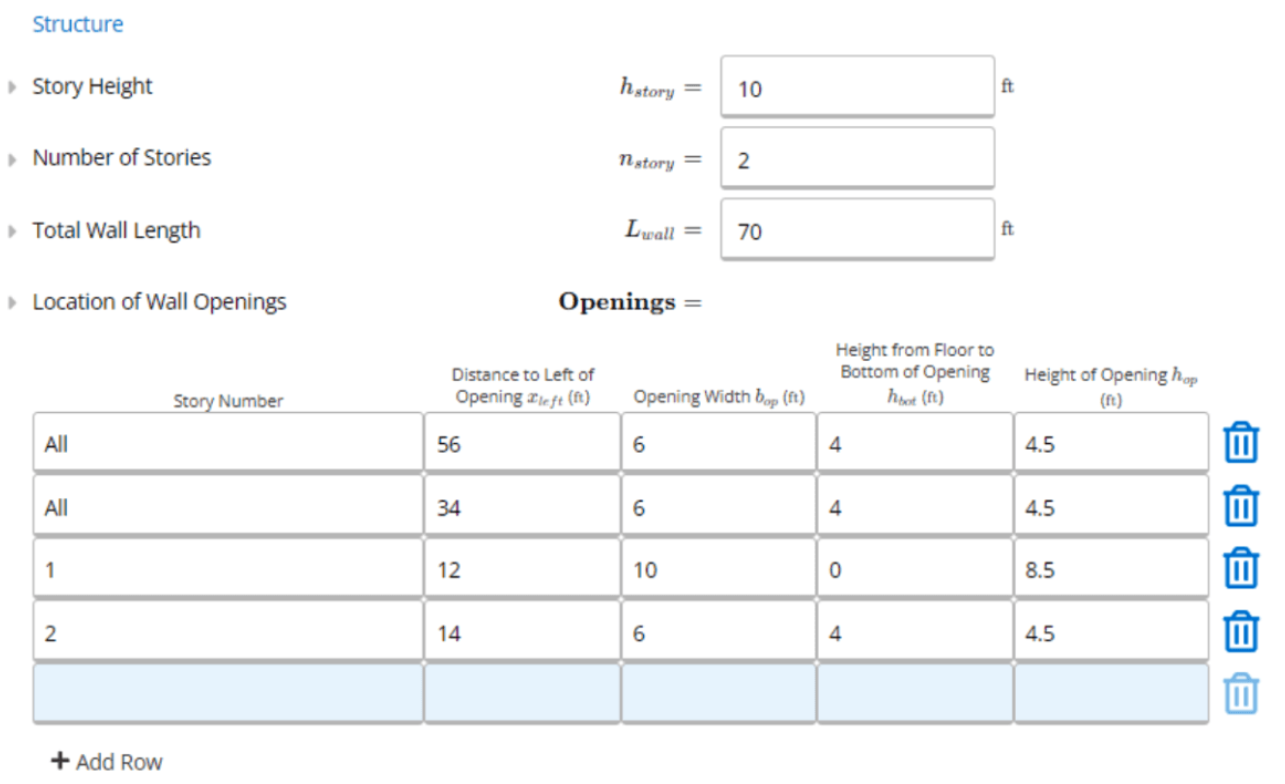
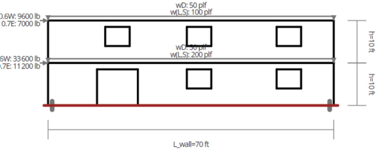
Two story building located in Portland, ORThe story height is 10 ft
The total wall length of 70 ft
Six openings, with three windows on the second floor and two windows plus a door on the first floor
Applied loads and location of wall openings can be seen in the diagram below
Entering Your Design Criteria
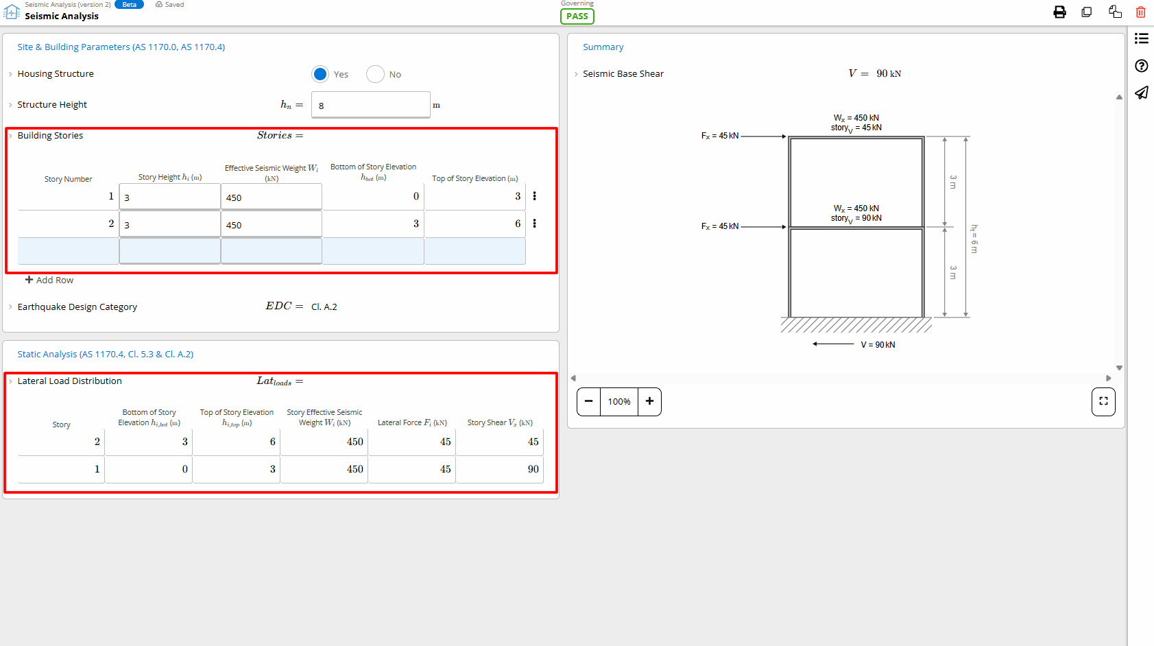
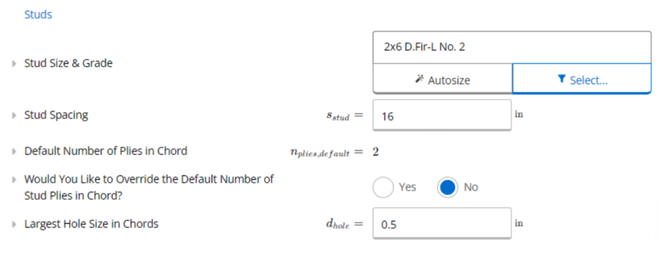
Our wall self weight is the weight of the sheathed wall. We can use a value of 12 psf, corresponding to a 2x6 exterior stud wall spaced at 16”. Next we can input our dead loads that counteract the overturning loads, transient loads (snow or live) that will contribute to compressive loads in the chords, as well as ultimate wind shear load and seismic loads which impacts the lateral loading. Our loads are specified at the story level, so we will calculate each load. We will assume we have 10 ft long joists framing into the wall so we can use a dead load of 10 psf. For this, we can calculate 10 psf multiplied by half the joist length (50 plf). We can do the same for a 20 psf transient live load on the roof, resulting in 100 plf, and a 40 psf transient live load on the first floor. Our ultimate wind and seismic shear loads should be inputted at the ultimate level, as Calcs.com will automatically factor them by 0.6 and 0.7 for wind and seismic loads, respectively. To determine these values a lateral load analysis should be completed, which can be done using our wind and seismic load calculators, in combination with our diaphragm analysis tool. For this example the final values are outlined in the background information. Inputting seismic loads will also prompt you to include a design spectral response acceleration at short periods. This SDS value can be found using our Seismic Analysis calculator. It is used to calculate the additional vertical loads from vertical motion during an earthquake. For this building in Portland, we can use SDS = 0.77.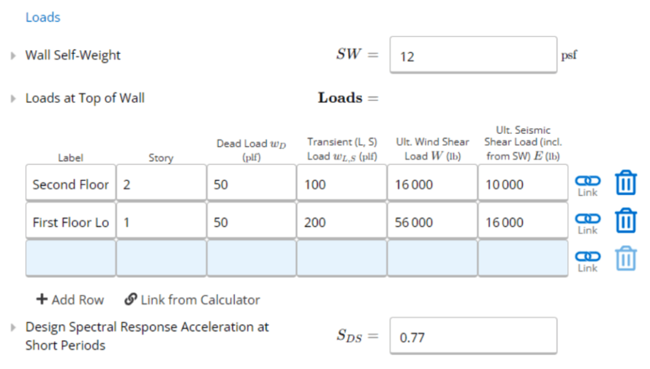
Optimizing Your Design
After inputting the loads and structure geometry, we can determine the required sheathing and studs required for a passing design. Our sheathing and nail pattern can be selected using the member selector, in which we can specify our sheathing material, thickness, as well as our nail size and spacing. These will govern the shear capacity of the wall. Thicker sheathing, or smaller nail spacing will result in higher shear capacity. For our design, we will select a 15/16” OSB/Plywood, 6d@2”. We can also specify if our wall is sheathed on one or both sides. This will design the shear wall with the same sheathing and nail pattern on either side, doubling the capacity. Since our capacity is above a passing utilization, we can design this to be sheathed on both sides. Similarly with blocking at the panel edges, we can fasten the edges of the panels to studs. An unblocked shear wall will have lower shear capacity. To help with the high shear demand, we can design a blocked shear wall. We can leave our nail spacing in field of panels at 12 inches. This value doesn’t have much of an impact on the strength, but is required as per the code.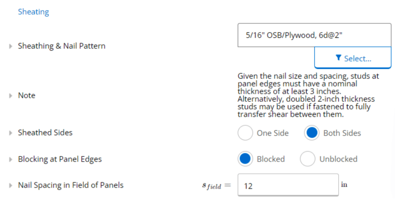
Interpreting Calculations and Results
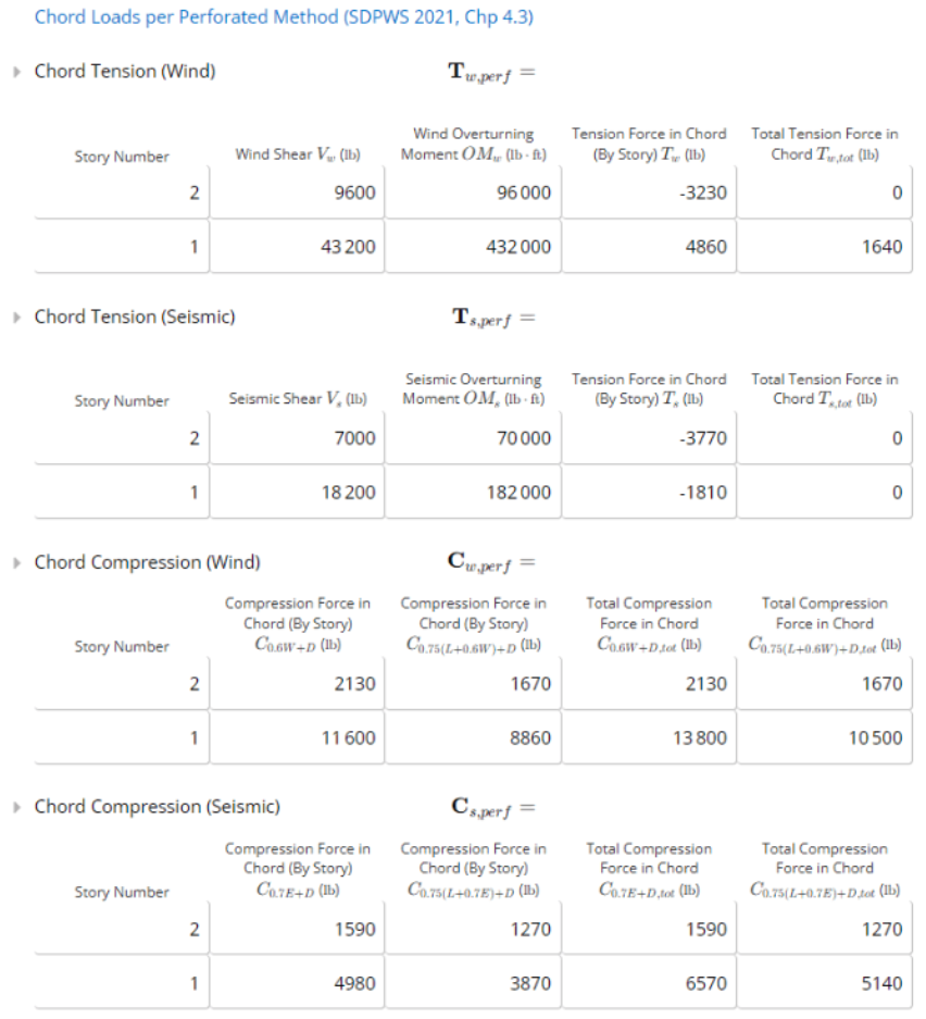
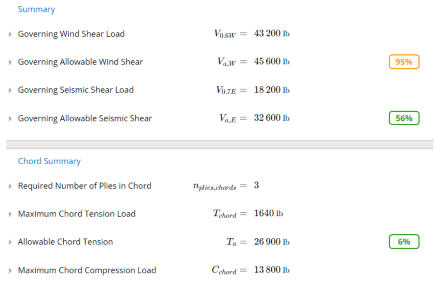
Under the shear capacity section, we can see how the capacity is calculated per story for wind and seismic conditions. For the perforated method, an adjustment factor is calculated per story based on the total area of openings and the total wall area. This factor accounts for a shear capacity reduction due to unsheathed areas or openings. The unadjusted capacity is taken from tables in the AWC SPDWS, and is determined based on the sheathing and fastener spacing. The capacity is then adjusted with the shear capacity adjustment factor (Co), the specific gravity adjustment factor and the effective width. For perforated shear walls, an upper limit of 2435 psf is applied to the shear capacity. The story with the highest utilization governs the shear design.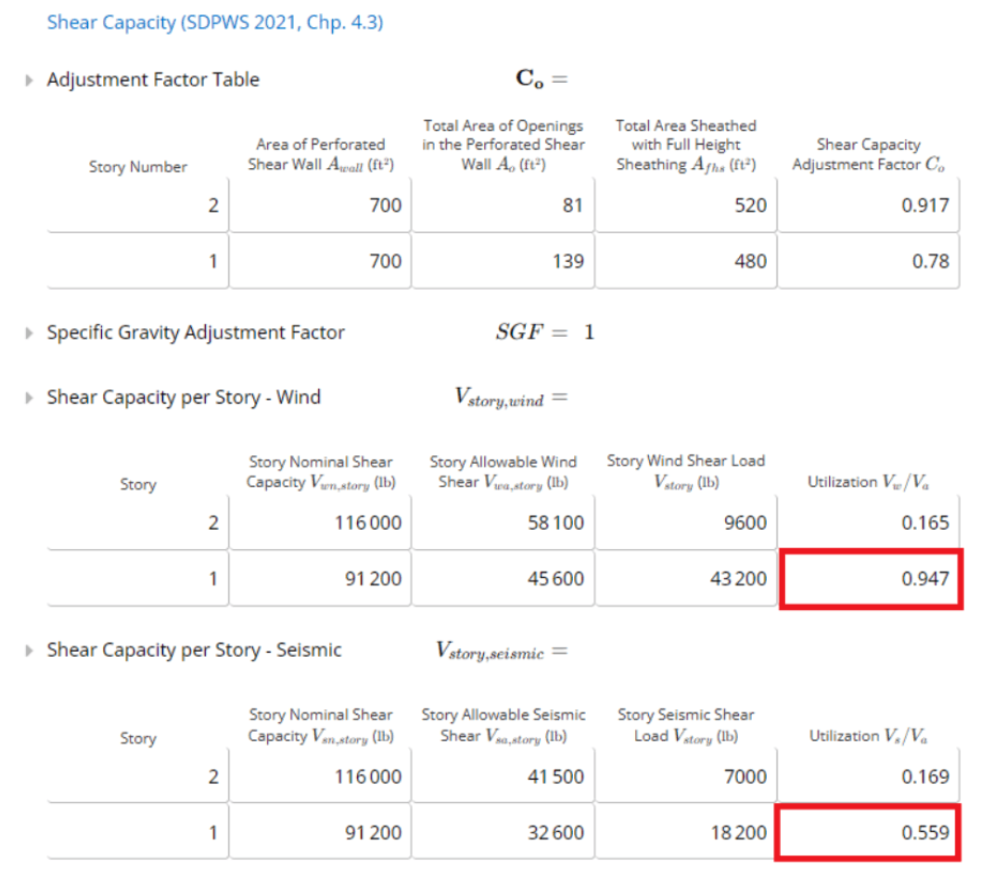
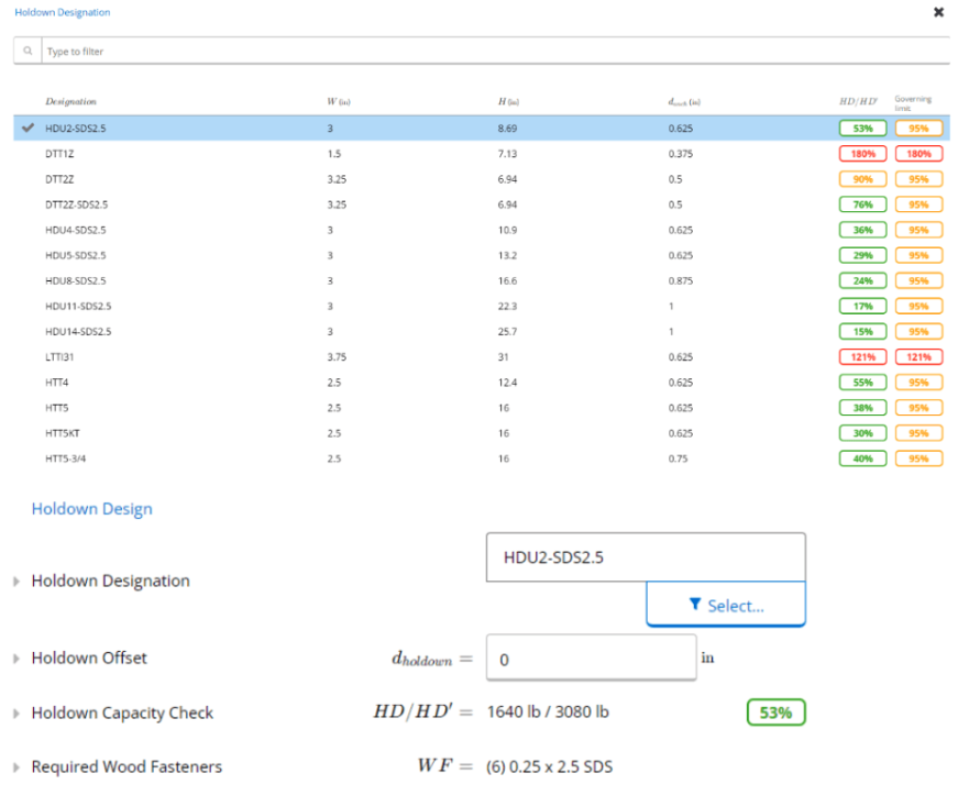
Holdown Design
Now that we have designed our shear wall, we can select the holdowns. Holdowns are required when there are overturning conditions that cause uplift in the chords. Calcs.com currently supports a selection of holdowns from Simpson Strong Tie. When we open the member selector, we can see the utilization for each. For this design, let’s use a HDU2-SD2.5. You can specify an offset distance, which would be the distance from the exterior face of the chord to the center of the holdown anchor rod. This value is considered for the moment arm and calculation of the tension and compression chord forces. From there, we can see the holdown capacity check and required wood fasteners. These values are both based on the Simpson Strong Tie catalog. For the perforated method, one benefit is that holdowns are only required at the ends of the walls, rather than at each opening. For this design, two HDU2-SD2.5 holdowns will be required at either ends of the wall.