

1. Seismic Map Data
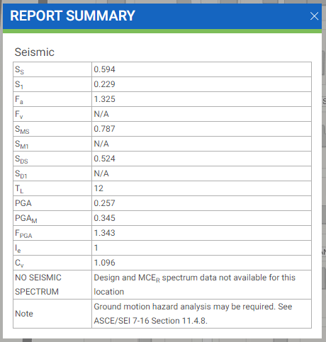
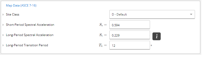
First, we identify the map data properties for our building. We can obtain the seismic map data from free tools such as the ASCE 7 Hazard Tool. Assuming our project is located at 2951 E Grant Ave, Fresno, California, 93701, we can specify the standard we are using, risk category, site soil class, and desired load types into the tool.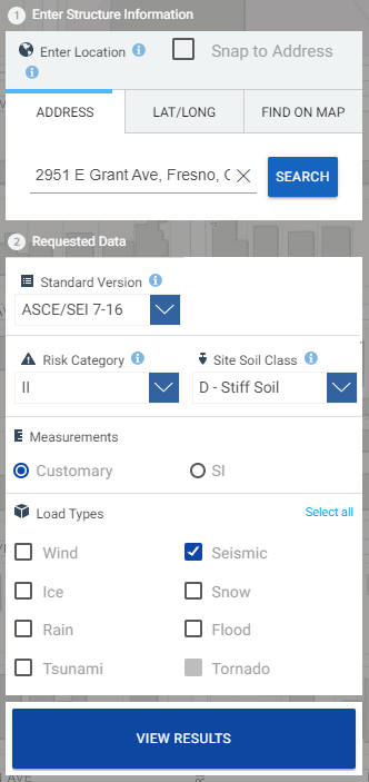
2. Key Building Properties
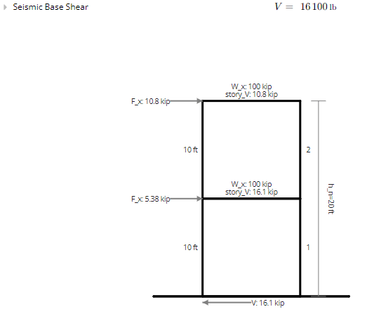
We now enter the key building properties based on the type of building we are designing for. Assuming the building is a 2-story building with 10 ft in height and 100,000 lbs (or, 100 kips) in seismic weight for each floor. We use light-frame (wood) walls sheathed with wood structural panels rated with shear resistance as our seismic force-resisting system.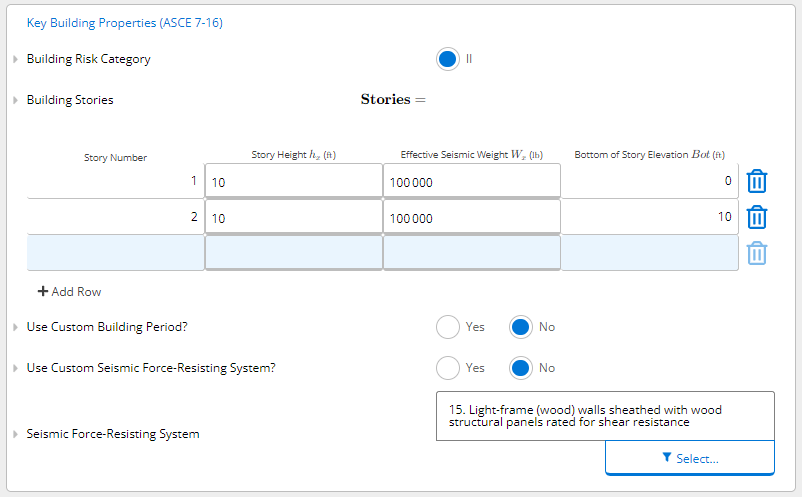
3. Summary of Results
Once we have input all the necessary data into the Seismic Analysis Calculator, we can quickly glance at the summary of results we need for designing a house, such as the Design Short-Period Spectral Acceleration (S DS), Design Long-Period Spectral Acceleration (SD1), as well as the Seismic Design Category (SDC), which is a helpful parameter to determine which analysis you can use in a seismic calculation (e.g., the equivalent lateral force method).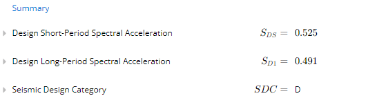
Additional code provisions (ASCE 7-16 and 7-22)
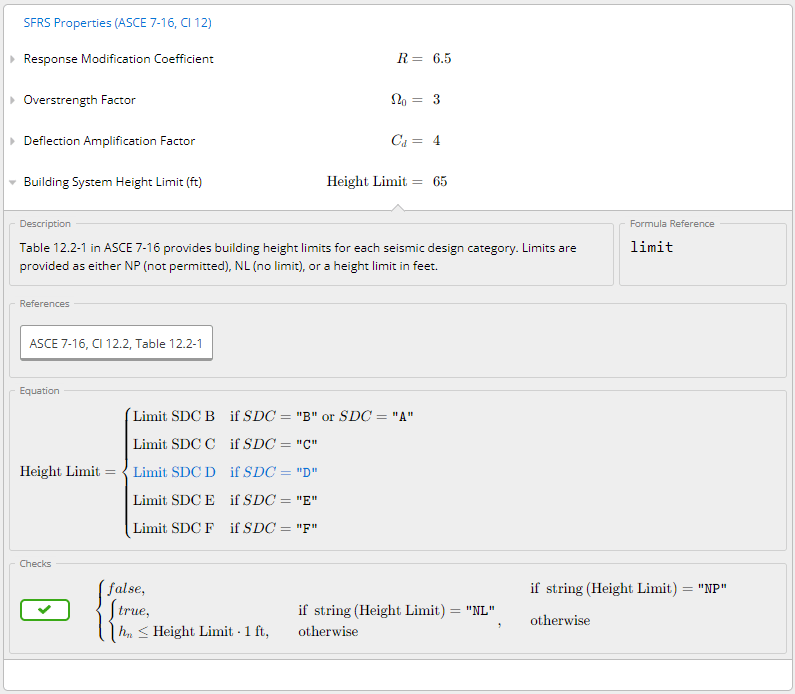
The Seismic Analysis calculators for both ASCE 7-16 and 7-22 also cover several additional code provisions directly, so you don’t need to fall back to hand calcs or side spreadsheets for the following cases. All new inputs default to No/automatic, so existing sheets return identical results.- Expanded Seismic Force-Resisting System (SFRS) list. The SFRS dropdown covers the full ASCE 7 Table 12.2-1, including steel special/intermediate/ordinary moment frames, eccentrically braced frames, buckling-restrained braced frames, ordinary reinforced concrete/precast/masonry shear walls (in both bearing-wall and building-frame categories), cold-formed light-frame walls, and steel systems not specifically detailed for seismic resistance. Each system carries its correct R, Ω₀, Cd, per-SDC height limits, and footnotes. Custom R/Ω₀/Cd values are still supported if your system isn’t in the table.
- Flexible-diaphragm overstrength reduction. Toggle on the flexible-diaphragm option and, when the tabulated or custom Ω₀ ≥ 2.5, the calculator reduces Ω₀ by 0.5 per Table 12.2-1 footnote b.
- Redundancy factor ρ. ρ is determined automatically from the Seismic Design Category (1.0 for SDC A/B/C, 1.3 for D/E/F per Cl 12.3.4), with a manual override for cases meeting Cl 12.3.4.2. It is reported and exported for use in downstream load combinations but is not applied to the prescribed forces here.
- Accidental torsion (Cl 12.8.4.2). An optional 1.10 amplification of the seismic base shear (and the derived story forces Fx/Vx), applicable to non-flexible diaphragms.