


Worked example
Example 1: simply supported beam
A simply supported reinforced concrete beam spans 3500 mm as an office building floor beam. The steps below follow the first example in the video underneath, with the same conditions.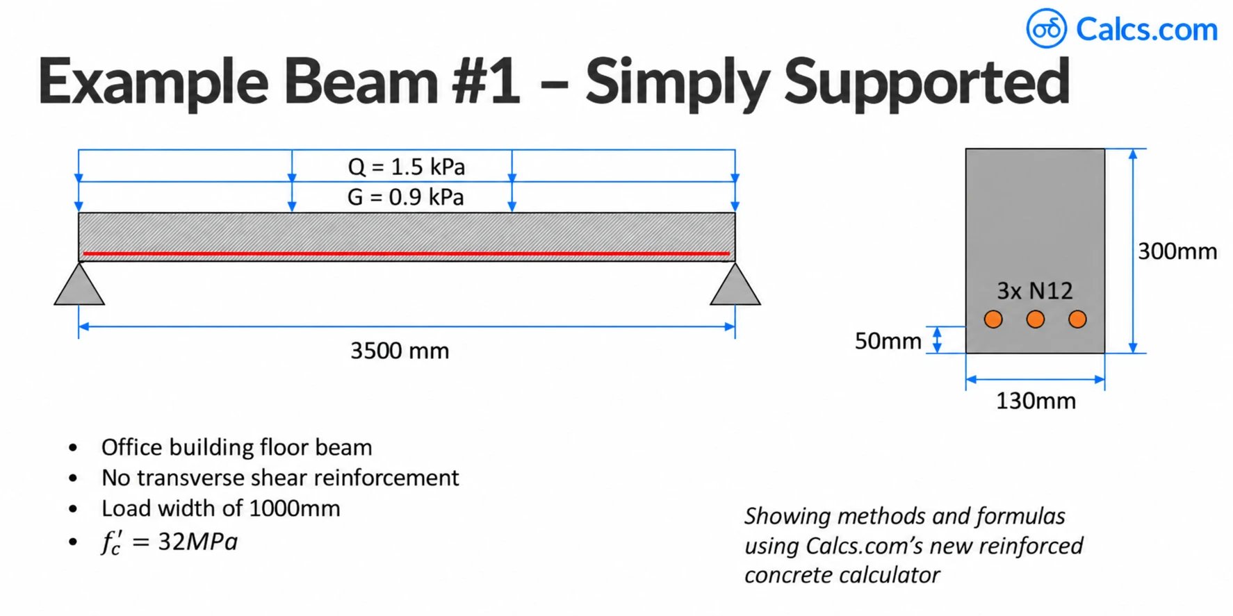
- Span of 3500 mm, simply supported.
- Permanent load G of 0.9 kPa and imposed load Q of 1.5 kPa, on a 1000 mm load width.
- Office building floor beam.
- Section 300 mm deep and 130 mm wide, with three N12 bars at the bottom and no top reinforcement.
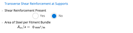
- No transverse shear reinforcement.
- Concrete strength = 32 MPa.
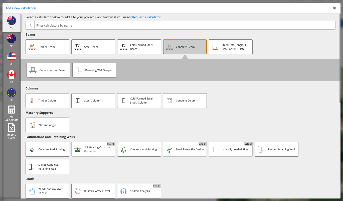
Open the Generic Indoor Beam preset
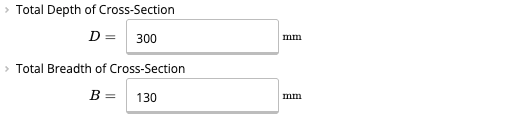
Set the section size
Check the concrete

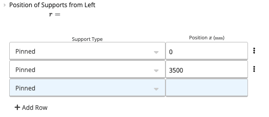
Set the length and the supports

Choose the bottom bars
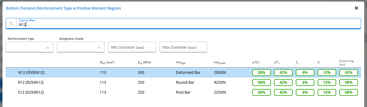

Enter the number of bars and the cover
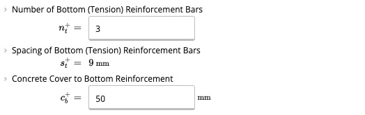
Remove the top reinforcement

Check the shear reinforcement
Check the floor load
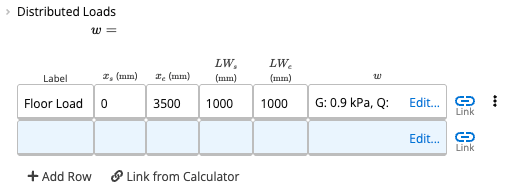
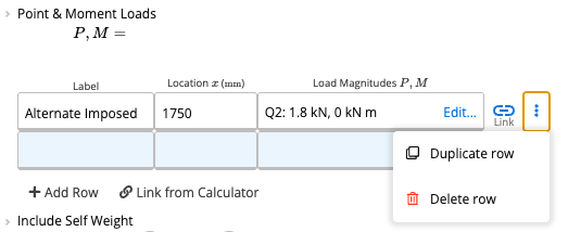
Remove the alternate imposed load
Set the character of imposed load

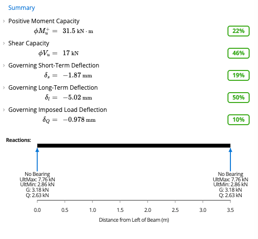
Read the results

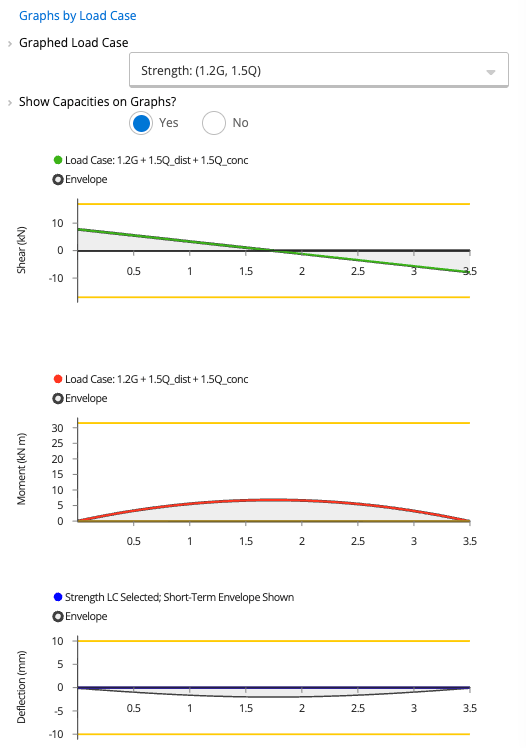
Look at the graphs
Inputs
Calcs.com output
Hand check
This is a sanity check on the moment and shear demands only. It uses the 1.2G + 1.5Q load case shown on the graphs, with L = 3.5 m. The sheet takes the shear at the support, so equals the ultimate reaction. Calculator version 125, Generic Indoor Beam preset.
Simply supported and continuous RC beam worked examples
The numbers spoken in the video are from an older recording. Shear at 42%, a concrete shear strength of 26 kN and a web-crushing strength of 259 kN match the calculator’s default cover of 30 mm, and 259 kN is the web-crushing strength from before Amendment 2 reduced it by 10%. The worked example above is calculator version 125 with the 50 mm cover, which gives shear at 46% and a governing long-term deflection of 50%. The transcript is left as spoken.Video transcript
Video transcript
So now moving on to some examples. We’ll do two different examples. One, a simply supported beam and two, a more complex beam.
Example 1: simply supported beam
First, we’re just going to take just about the simplest possible beam you can imagine. There’s only tension reinforcement, simply supported, 3.5 meter total span.
We’re going to have an imposed load and a permanent load on it equal to one point five and zero point nine kilopascals, respectively.
We’ll assume this beam is in an office building that’s affecting the character of the imposed load.
We’re going to assume no transverse reinforcement, a load width of a simple flat one meter, and concrete strength of 32 megapascals.
Now we’re going to show the how the methodology and formulas work using our new reinforced concrete calculator in ClearCalcs [Now Calcs.com].
So I’ll load up my web browser.
And just go over to clearcalcs.com [Now Calcs.com].
And I’m gonna create a new project, just call it webinar for now, and add in a rectangular concrete beam on here.
So at the top here, we’re making similar assumptions to what I described in our webinar already. No torsion, no prestressing, and let me assume that, basically, you’re gonna be checking all the detailing on your own.
That’s not checked in this sheet.
So, for the simplified beam, our total dimensions were 300 depth, 130 millimeter, total breadth, 32 megapascal concrete, 3.5 meter length, and we said we only have tension reinforcement consisting of three N12 longitudinal beams, so no top reinforcement, no transverse reinforcement, a one meter load width with point nine and one point five kilopascal dead and live load respectively.
We’ll keep self weight in there.
Character of imposed load, we said this was an office building, and usually you’d be considering wind and some other loads as well. I’m going to be removing those from this just to simplify everything.
Again, we’ll address complex loading later on in another webinar some other time.
And then we end up with final results.
75% of our total capacity calculated. Our controlling factor is long term deflection and you can see how demands and capacities relate to each other in a summary box at the top here.
This sheet is going to follow through the full procedure we just described. So flexural strength calculated midspan. It’s going to calculate your uncracked neutral axis location and depth to neutral axis with Ku.
You’ll notice similar formulas as is… As we went through in the webinar earlier.
This is as typical an under reinforced beam.
Shear analysis, I mentioned that Vu max is not usually going to govern for you. Here, it’s calculated as 259 kilonewtons, whereas our capacity of the concrete is 26 kilonewtons, so we’re very far off from that web crushing limit actually occurring. That’s typically going to be the case for you.
And deflection analysis, calculating the effective second moment of area, and we have just our quick stability checks at the end as well.
So we see that moment is pretty far from governing, shear is at 42%.
If we had a whole… Had roughly double that shear, we may want to consider starting to add some fitments, but in the end, it’s going to be the long term deflection that’s governing here.
Example 2: more complex beam
So then going to our second example, that’s gonna be a more complex beam.
We’re going to assume that the first beam we calculated is resting on top of our more complex beam at a location of seven meters. We have a total 10 meter span length… Or, excuse me, total 10 meter beam length with spans of 3.5 meters, 4.5 meters, and then a cantilever on the end of two meters.
We’ll have two different sets of reinforcement that differ between positive moment and negative moment, N12 bars on the top and N10 bars at the bottom.
In positive moment regions, we’ll have three N10s at the bottom and just two N12s at the top.
Negative moment regions will have three N12s at the top and two N10s at the bottom.
This time, we’ll assume it’s a retail building. We’ll put in some basic R6 shear fitments at 200 millimeter spacing, increase our load width a little bit to 1.5 meters, and we’ll again use a 32 megapascal total concrete strength.
So going back into our calculator, duplicate that to… So we don’t need to reenter in our section shapes, which is the same depth of 300 millimeters and a 130 millimeters.
This time, our total beam length is 10 meters, so we’ll put in that.
Supports at 3,500 millimeters and 8,000 millimeters for our three point five and four meter… And 4.5 meter spacing. You can see those shown graphically in the lower right here.
So we were going to have N10s on the bottom and N12s on the top.
This time, we are including top reinforcement in positive moment regions in the mid spans here, but we have three longitudinal reinforcement beams on the top and two on the bottom.
Shear fitments, we are going to include those R6s at 200 millimeters.
These are going to be typical standard fitments that have two legs, just your standard closed rectangular fitment, and 90 degrees for a perpendicular fitment.
And then this time we do have differing reinforcement in negative moment regions, So this is going to copy from up… What we already entered up above, but we’re going to modify it a little bit for our negative moment regions to instead have three top reinforcements and two bottom reinforcements.
Same loading, except we’re going to increase load width to 1,500 millimeters, and we’re also going to link in previous beam that we calculated and all the reactions due to that and put that in at seven meters.
We then have a retail character imposed load instead of an office character imposed load and including self weight as normal.
And you notice at the top here that we do have a failure due to our stability checks.
Scroll down here. Our default assumption for stability checks is incorrect for a multi span beam, so we just need to enter in that it’s 4,500 millimeters, the maximum length of our span, and that works just fine. We no longer have a failure there.
We can see again here that we’re making a bit more productive use of our flexural capacity. Still a lot of space there, but we’re only… But we’re using about a third of our flexural capacity in both cases.
Deflection is what’s going to be controlling for us. We have a yellow shown here for being above 90%, but that still works and making a bit more use of our shear capacity here at 54%.
Method & scope
See the exact clause
Calculation method
The Concrete Beam calculator designs rectangular reinforced concrete beams to AS 3600:2018 (Amendment 2) using limit state design. A live FEA engine resolves internal forces for unlimited span and load configurations, and checks are performed for flexure, shear, and deflection at critical sections.Flexural capacity (AS 3600:2018, Cl 8.1)
Positive and negative moment capacities are computed using the rectangular stress block. For a singly reinforced rectangular section: where is the depth to the tensile steel and is the neutral axis depth ratio. The stress-block depth factor, with in MPa, is The capacity factor is from Table 2.2.2. For N-class reinforcement and no axial force: A ductile section reaches 0.85. L-class bars are held at 0.65. The factored capacity is . Minimum reinforcement (Cl 8.1.6.1) is enforced: where is the flexural tensile strength of concrete.Shear capacity (AS 3600:2018, Cl 8.2, simplified method)
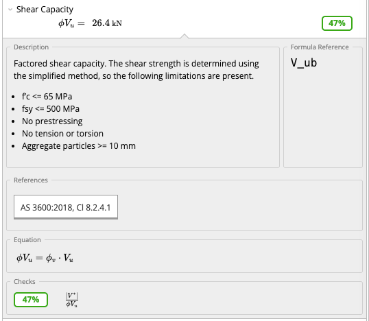
Concrete shear strength (Cl 8.2.4.1), within the limits of Cl 8.2.4.3: is capped at 8 MPa. Where the fitments are below the minimum, and is in millimetres: Otherwise . The simplified method applies when MPa, MPa, with no prestress and no tension or torsion. The ultimate shear strength is For vertical fitments, , and the simplified method takes . With no fitments, and . With N-class fitments at or above the minimum, and below , (Table 2.2.2). The factored capacity is .Deflection checks (AS 3600:2018, Cl 8.5)
Three deflection limits are verified:- Short-term deflection: using the effective second moment of area under short-term service loads
- Long-term deflection: adding a creep/shrinkage multiplier to the sustained-load deflection
- Imposed load deflection: deflection due to live load only, checked against the imposed deflection limit
Assumptions
The eight items in the Key assumptions row are the list under the calculator’s Sheet Details. No torsional demands are considered. Prestressing and post-tensioning are not included. Secondary effects on shear () and load reversal are not considered. Beams are assumed to be enclosed within the building. Concrete detailing (bar laps, anchorage, hooks) is checked separately (see Cl 4, 5, 8.3, and so on).Symbols
The names below are the labels the calculator shows in its inputs and Summary.How to use it
Open the calculator
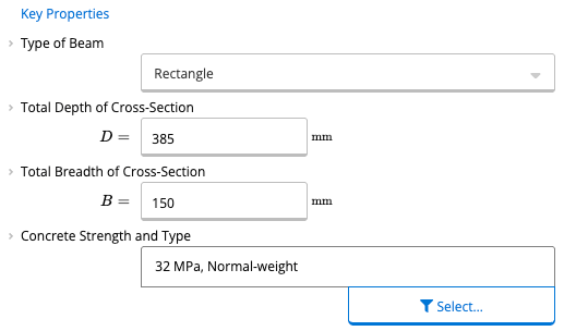
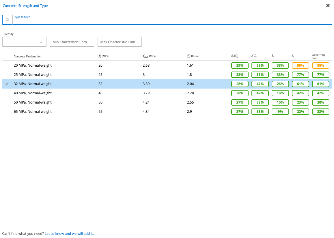
Set the section and the concrete
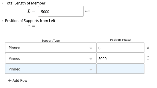
Enter the length and the supports
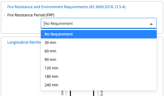
Set the fire resistance
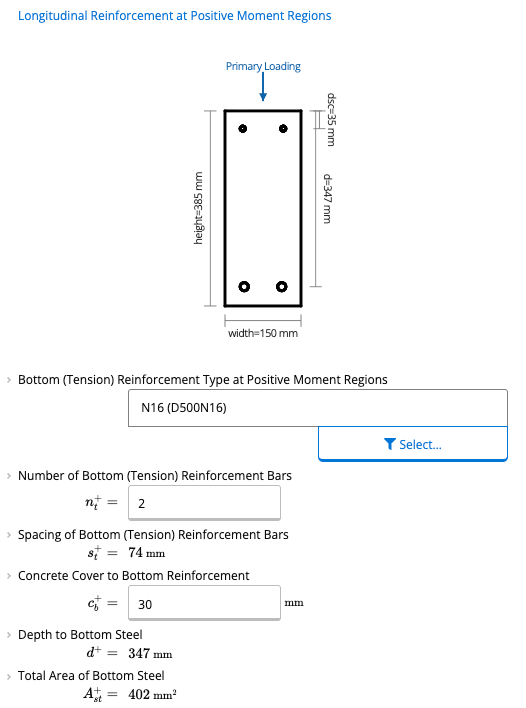
Enter the bottom reinforcement
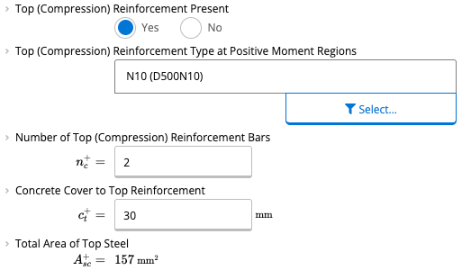
Enter the top reinforcement
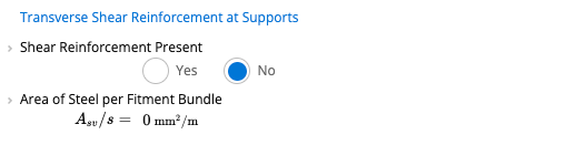
Add the shear reinforcement
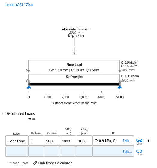
Add the distributed loads
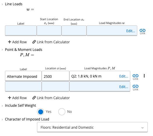
Add line, point and moment loads
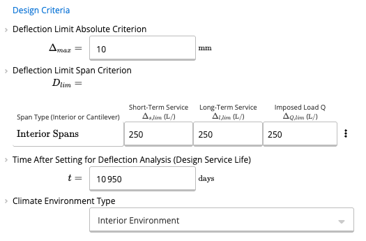
Check the design criteria
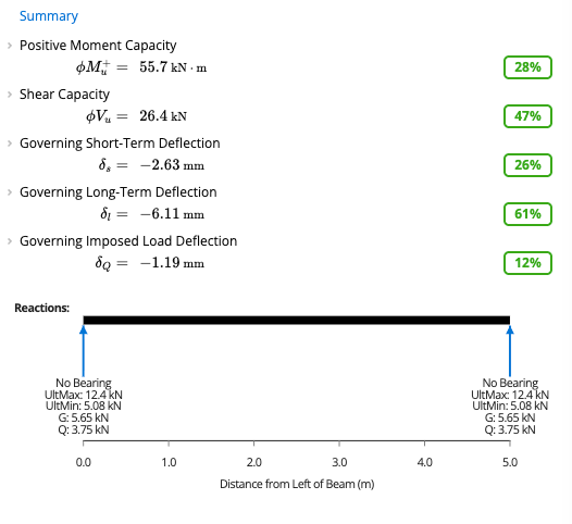
Read the summary
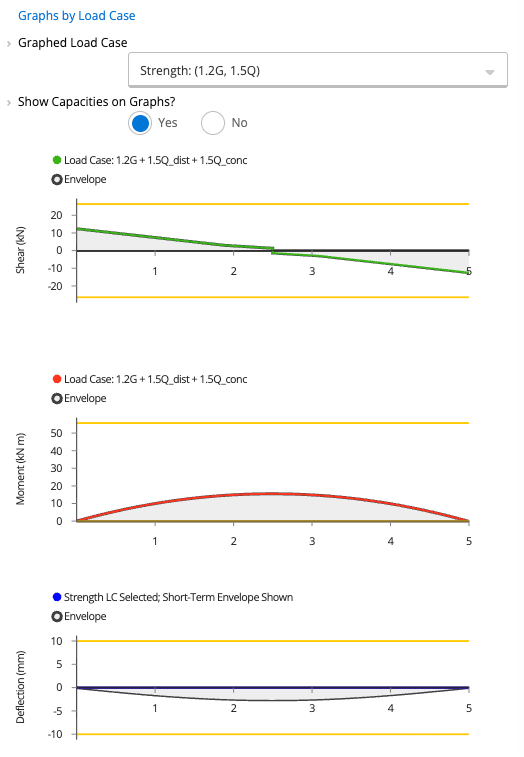
Check the graphs by load case
Open a result to see its clause
Review the results and export
Available presets
Each preset opens the calculator with a typical setup already entered.Common questions
What design standard and method does this calculator use?
What design standard and method does this calculator use?
What are the key inputs?
What are the key inputs?
What checks does the calculator perform?
What checks does the calculator perform?
How is the effective second moment of area calculated for deflection?
How is the effective second moment of area calculated for deflection?
What shear assumptions apply?
What shear assumptions apply?
How does load linking work with column and footing calculations?
How does load linking work with column and footing calculations?