


Worked example
Example 1: simply supported beam
A simply supported cold-formed steel beam spans 3000 mm as an office building floor purlin. The steps below follow the first example in the video underneath, with the same conditions.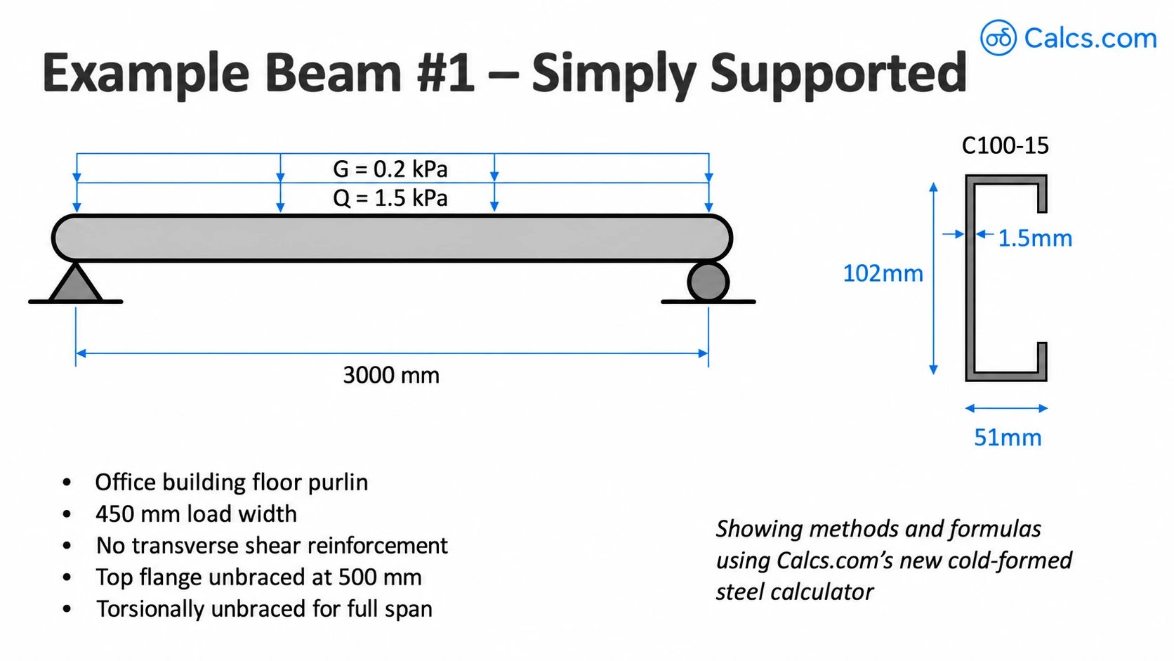
- Span of 3000 mm, simply supported.
- Permanent load G of 0.2 kPa and imposed load Q of 1.5 kPa, on a 450 mm load width.
- Office building floor purlin.
- No transverse shear reinforcement.
- Top flange unbraced at 500 mm, and torsionally unbraced for the full span.
- Section C100-15.
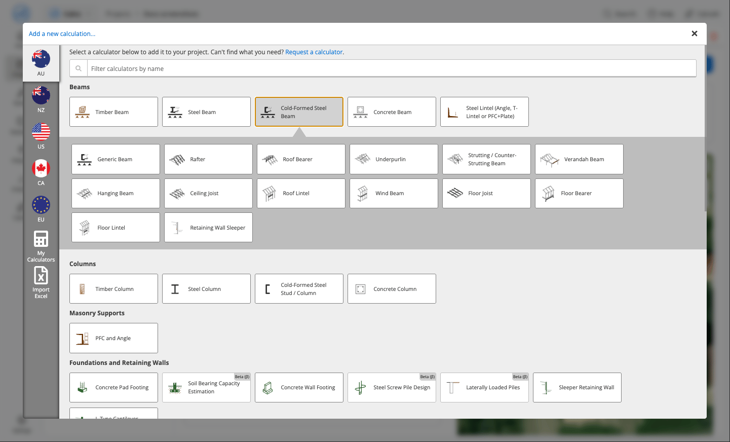
Open the Floor Joist preset
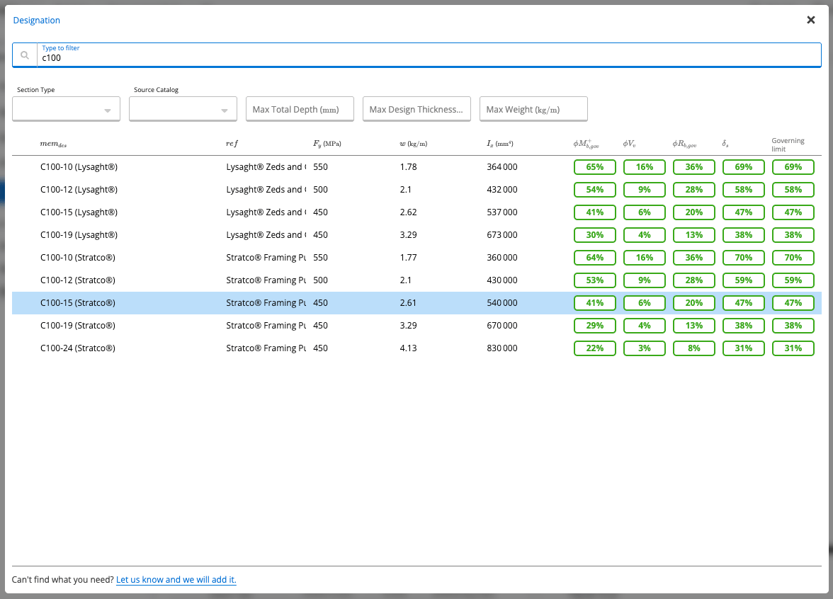
Select the section
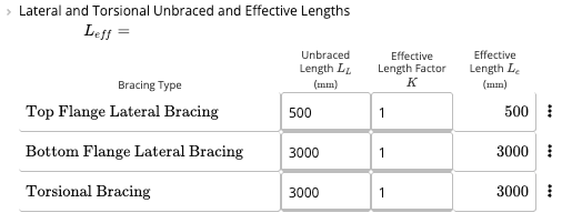
Set the length and the top flange bracing

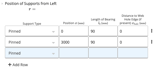
Check the supports
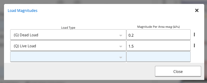
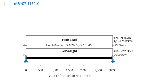
Enter the loads
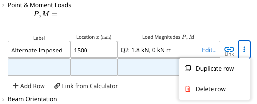
Remove the alternate imposed load
Set the character of imposed load

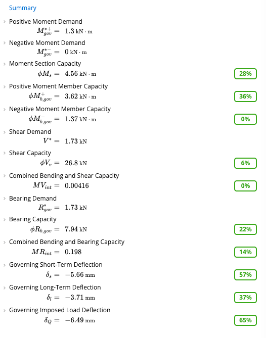
Read the results

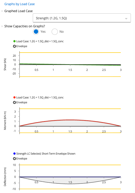
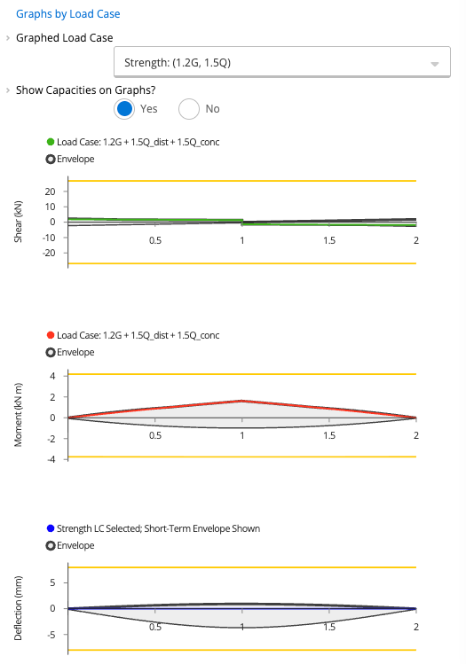
Look at the graphs
Inputs
Calcs.com output
Hand check
This is a sanity check on the moment and shear demands only. It uses the 1.2G + 1.5Q load case shown on the graphs, with L = 3 m. Calculator version 125, Floor Joist preset.
Simple and Complex Beam Worked Examples
Video transcript
Video transcript
So now going on to some example calculations for beams.
Example 1: simply supported beam
Our first example we’ll make use of is a simply supported beam. Just one of the simplest examples you can make use of.
We’re going to assume that it only has permanent load and imposed load, a G of point two kilopascals and a Q of 1.5 kilopascals. We’re going assume it’s just a three meter beam.
Assume it’s an office building for the purpose of the character of the imposed load. 450 millimeter load width. We’re gonna assume it does not have any transverse shear reinforcement.
That the top flange has bracing at 500 millimeters and that there’s torsional bracing only at the very ends of the beam. So the full span length is equal to the torsional brace length.
We’ll use a C100-fifteen section.
That’s a section produced by both Stratco and Lysaght.
The first number in there is the nominal height of the web. So it’s actually 102 millimeters, nominal 100. The second number in there, 15, refers to the thickness of the web, of the entire cross section. So 15 is 1.5 millimeters.
For this type of section, your flange width is 51 millimeters.
We’ll use ClearCalcs [Now Calcs.com] as our means of providing this example. So I’ll open up my web browser, go to clearcalcs.com [Now Calcs.com] and log in.
We’ll create a new project, just call it webinar here.
First project for webinar clients, let’s say.
And I’ll add a calculation for a cold form steel beam. We have a number of choices for different types of cold form steel beams.
These just give you different default loads and default support conditions and default restraints depending upon exactly the type of beam being used here. We said this was a floor system, so I’ll select floor joist in this case.
So that’ll open up our design sheet here.
We said that the total length is three meters or 3,000 millimeters.
And page loaded there.
Top flange bracing is 500 millimeters.
And we said that the bottom flange bracing and the torsional bracing would just be equal to the total unbraced length of 3,000 millimeters.
Simply supported beams, so we have restraints only at the start and end of the beam.
It’s a permanent load of 0.2 kilopascals and imposed load of 1.5 with a load width of four fifty millimeters.
A character of imposed load, this is the office building we said, so it’s floor office.
By default, we’re including the alternate imposed load which AS eleven seventy point two [correction: 1170.1] calls for.
For simplicity of the analysis here, I’m just going to remove that from our calculation just to make the graphs here make a bit more sense.
But, so then you see we are still on the C150-fifteen. We’re using a C100-15 section for this calculation.
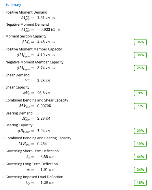
So from that, we get our overall results here.
Positive and negative moment demands and capacities with our section capacity and the member capacities.
Shear demand and shear capacity, we are allowing you within our calculation here to include members with holes. I say I did not go through all the details of those calculations within this webinar but you can include that in our calculation sheet here.
The bearing or web crippling demand capacity and then bending shear and bending bearing interaction values as well.
Our most closely governing value here is deflection where we have a deflection of 9.2 millimeters with a limit of 10 millimeters. So just within our allowed limits.
We have all of our charts here showing the shear moment and deflection.
By default, we’re showing you the governing load case, which is 1.2 gs times 1.5 plus 1.5 q.
We can select other possible load cases here such as 1.35 gs and that will refresh and show a lower value within the envelope.
Or we can also look at individual loads alone.
So looking at live load alone, you can see the moment that results, moments in shear that results from those as well as the deflection that results from live load alone.
So for a simply supported section, if you want to assign a moment connection to both ends, such as if you have a fully fixed section, then we allow you to just select simply pinned or fixed for support type.
You can also apply a concentrated moment within table here if you want if you have a moment that you’re applying as well.
And as to what constitutes a moment connection for a cold form steel beam, Two bolts with a cleat is, would definitely be considered simply supported.
This is engineering judgment as to what you would consider to be a fixed connection.
The questioner here asks if four bolts within a single member at the end might be considered a fixed connection.
My opinion as an engineer is yes, probably it can be but that’s your call as a professional engineer to decide whether that would be considered a fixed or a pinned or something in between connection.
Alright, so that is our first example.
Let’s go back to the presentation.
Example 2: beam with multiple supports
And for our second example, we’ll have a more complex beam here.
We’ll have multiple supports, still keep them as pinned supports, but we’ll have the same loading, zero point two and one point five kilopascals for permanent and imposed loads.
We’ll apply that over the full length of the beam.
So the total length of the beam will make 10 meters with two meters between the first two supports and five and a half meters between the second two supports.
That leaves us with a two and a half meter cantilever at the end.
Same assumptions we’ll keep for simplicity here of an office building floor purlin, no transverse shear reinforcement, keep the load width the same.
We will add some additional bottom flange and torsional bracing at one meter on center spacing and we will need to use a slightly bigger member for this. We’ll use a C150-19 for this design.
So for doing that calculation, for simplicity, I’ll just duplicate the existing calculation that I have here and just modify that.
So we said this was going to now be a 10 meter beam.
We can use simple formulas in here.
So I’ll just say 10 times 1,000, 10 meter beam and that will do the calculation for that.
We said that bottom flange and torsional bracing would be 1,000 millimeters spacing. We’re keeping the same top flange bracing at 500 millimeters.
This time we have supports at 2,000 millimeters and at 7,500 millimeters.
We’ll keep the same bearing length of 25 millimeters just for simplicity again.
Our loading parameters all stay the same and as you can see here, the existing section C100-15 is insufficient. We get failures in our moment capacity, in our moment and bearing interaction capacity as well as in our deflection.
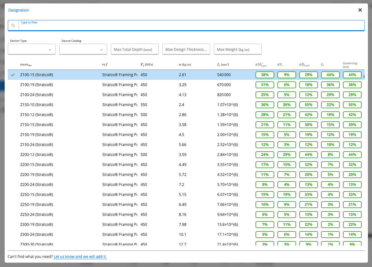
But we can get a quick view of what works and what doesn’t by opening up the member selector here.
So in this case, we’re going look and see a C150-19 is a fairly efficient section that works.
And we can see that that opens up and shows us a working section.
We can additionally load link in our other beam here.
So say that our other beam is resting on top of this beam, I can load beam b one, select it here and put in a location for it, let’s say at 4,000 millimeters.
And you can see how that modifies then our graph here.
We’re still showing the live load alone, so hence all of our graphs show an intermediate value within the envelope, within the load case envelope.
And we do check all load cases simultaneously here. So if you want to see individual load cases, you can open up charts here. You can see every strength load case, the shear moment and reaction that results from each of those.
You can see the unfactored load values.
We only have permanent and imposed loads here, so all other types of loads have zero results.
And all of our calculations for member section capacity, member moment capacity, all contained within all of the subsections here that you can open up.
Global buckling, for example, we can look at more detail on this as well.
We can see that our global buckling capacity, we are using the first of the equations in the conditions. Our M naught is greater than 2.78 times MY so we’re using MY and we can see the references for these equations.
Right now this sheet is still using AS46002005. We’ll be updating it to 2008 by the beginning of next week.
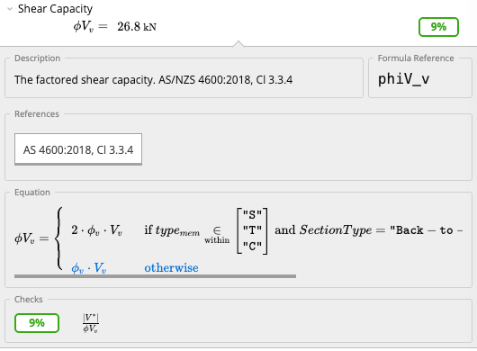
And similarly, you can open up everything else in here, see exactly what equation is being used.
Our distortional buckling capacity is making use of a more complex equation for distortional buckling.
And similarly for all of our shear capacities, our bearing capacities, in this case, you can open up bearing capacity and see a table of all of the different types of bearing that exist. So our first support is an end condition, bearing type one on this table and the other supports are interior conditions labeled as bearing type 1.1 on this.
You can see the reactions that occur at each of those, the capacities for each of those locations and the overall demand capacity ratios.
And again, everything summarized over on the right.
So a question of whether the added beam that we put in there for B1 is providing lateral bracing.
The calculation on this sheet right now is basing all of its excuse me, is basing all of its lateral, bracing calculations upon the first table that you have here. So assuming you are lateral bracing at the top flange, 500 millimeters, bottom flange, 1,000 millimeters and torsional, 1,000 millimeters.
We don’t currently let you within our calculations set what the specific locations are of the bracing where this taking the maximum worst case values.
But typically if you are connecting a beam there, you are going to have lateral bracing.
Method & scope
See the exact clause
Calculation method
The Cold-Formed Steel Beam calculator designs CFS beams using the Direct Strength Method (DSM) per AS/NZS 4600:2018 Cl. 7. Rather than the traditional effective width method, DSM uses Finite Strip Method (FSM) analysis to calculate elastic buckling moments for all relevant modes, then applies DSM strength curves to determine design capacities.Section moment capacity (AS/NZS 4600:2018, Cl. 3.3.2)
The section moment capacity is computed from the FSM-determined local and distortional buckling loads and the full cross-section yield moment . For back-to-back or boxed beam configurations, section capacity is doubled.Member buckling capacity (AS/NZS 4600:2018, Cl. 7.2.2)
Three member buckling checks are performed separately using the DSM interaction curves:- Global (lateral-torsional) buckling (Cl. 7.2.2.1): capacity from FSM global buckling load, accounting for unbraced length and moment gradient
- Local buckling (Cl. 7.2.2.2): capacity based on interaction between local and global modes
- Distortional buckling (Cl. 7.2.2.3): capacity based on the distortional buckling load from the FSM signature curve
Shear capacity and web holes (AS/NZS 4600:2018, Cl. 7.2.3)
Shear capacity is checked at the critical section. If web holes are present (depth , spacing ), a reduced shear capacity is also checked at the hole locations. No web holes are permitted within bearing lengths.Bearing capacity (AS/NZS 4600:2018, Cl. 3.3.6)
Bearing (web crippling) capacity is checked for reactions at supports and concentrated loads, based on section type and bearing length. Bearing is only checked for standard Cee or Zed sections bent about the X-X axis.Combined bending and shear (Cl. 7.2.3.5) and bending and bearing (Cl. 3.3.7)
Interaction checks are performed where both effects are significant: utilization (MV) = combined interaction ratio ≤ 1.0 utilization (MR) = combined interaction ratio ≤ 1.0Deflection analysis (AS/NZS 4600:2018, Cl. 7.1.4)
Deflections use an effective second moment of area that accounts for local and distortional buckling under service loads. Short-term, long-term, and imposed-load deflections are each checked against span/limit criteria.Symbols
The names below are the labels the calculator shows in its inputs and Summary.How to use it
Open the calculator
Choose the section
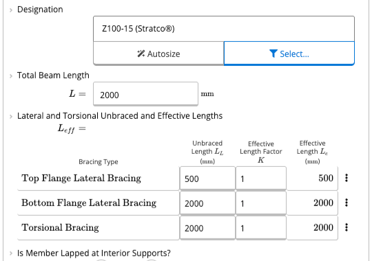
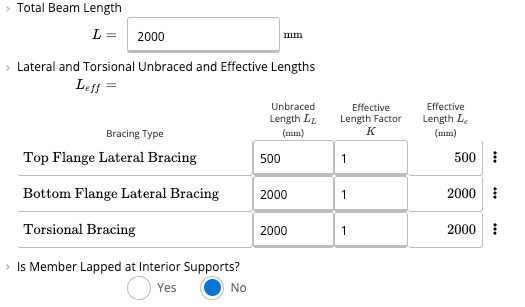
Enter the beam length and bracing
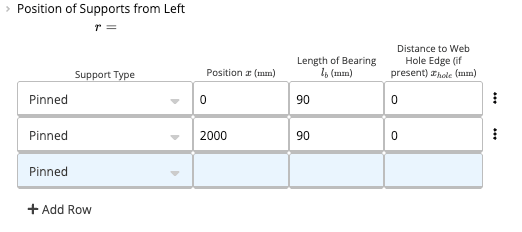
Enter the supports
Set the web holes

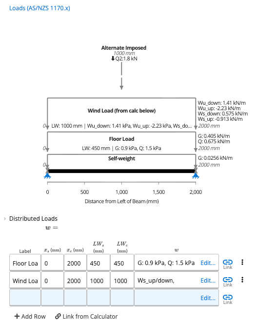
Add the distributed loads
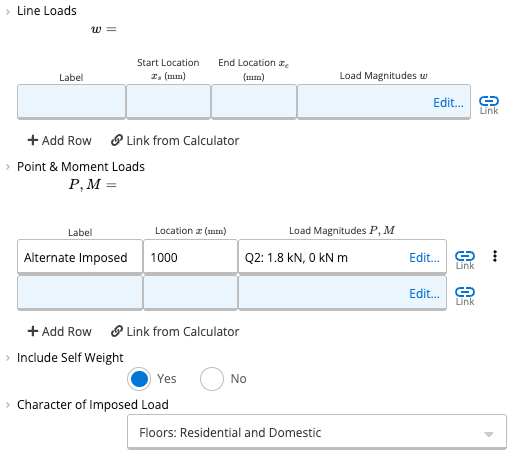
Add line, point and moment loads
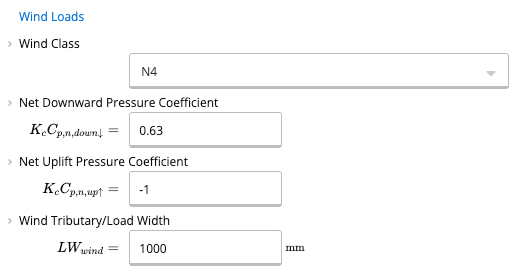
Set the wind loads
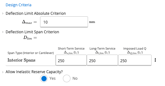
Check the design criteria
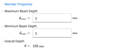
Set the member depth limits
Read the summary
Check the graphs by load case
Open a result to see its clause
Review the results and export
Available presets
Each preset opens the calculator with a typical setup already entered.Common questions
What design method and standard does this calculator use?
What design method and standard does this calculator use?
What are the key inputs?
What are the key inputs?
What does the calculator check and output?
What does the calculator check and output?
What CFS section types are covered?
What CFS section types are covered?
How does load linking work for CFS beams?
How does load linking work for CFS beams?