All regions

Beam Analysis

Run the calc
The Calcs.com Beam Analysis Calculator computes bending moment, shear force, and deflection along a single or multi-span beam using linear-elastic finite element analysis. Enter the span, section properties, supports, and loads, and it returns the maximum demands and the full diagrams. It handles cantilevers, continuous spans, and combined point, distributed, and applied-moment loads.

Worked example

Example 1: simply supported beam with a point load

A steel beam is 12 m long, pinned at the left end and on a roller at the right end. It carries one 8 kN point load, 9 m from the left support and 3 m from the right support. The loads and results follow a textbook example (R.C. Hibbeler, Structural Analysis, 8th ed., 2012) that Calcs.com uses as a test case for this calculator. The conditions are:
  • Simply supported beam, 12 m long, pinned at the left end and on a roller at the right end
  • One point load of 8 kN at 9 m from the left support
  • EE = 200 GPa and II = 60 × 10⁶ mm⁴, so EIEI = 12 000 kN·m²
  • Find the support reactions, the maximum shear and moment, and the maximum deflection
1

Add the Beam Analysis calculator

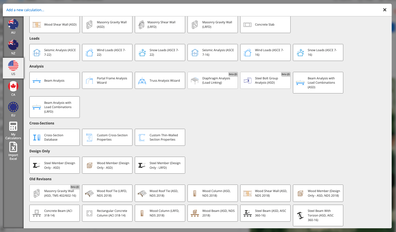
In your project, choose Add New Calculation, then choose Beam Analysis under Analysis.Add a new calculation window with the US region selected and the Analysis group listing Beam Analysis, Portal Frame Analysis Wizard, Truss Analysis Wizard, Diaphragm Analysis (Load Linking), Steel Bolt Group Analysis (ASD) and Beam Analysis with Load Combinations.
2

Enter the section properties

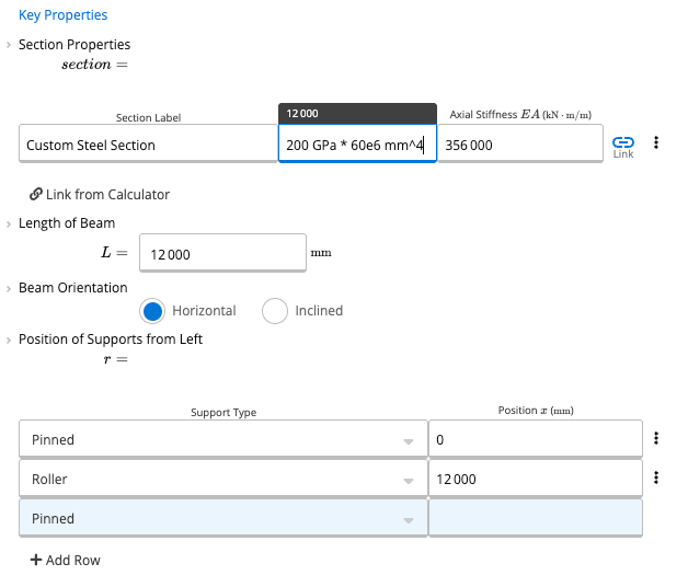
In Section Properties, the Bending Stiffness EIEI starts at 1332. Replace it with the formula 200 GPa * 60e6 mm^4. The calculator converts it to 12 000 kN·m². The example gives no axial stiffness, so EAEA stays at its default of 356 000, and the Section Label stays as it is.Key Properties with the Bending Stiffness field being edited, the formula 200 GPa * 60e6 mm^4 typed in and a tooltip showing 12 000, an Axial Stiffness of 356 000, a Length of Beam of 12 000 millimeters, Beam Orientation set to Horizontal, and supports of Pinned at 0 and Roller at 12 000 millimeters.
3

Set the length and the supports

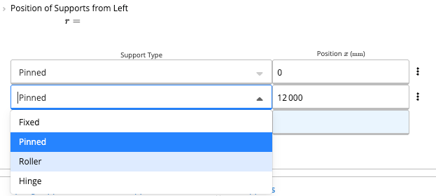
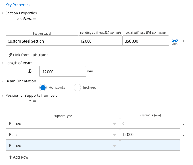
Enter 12 000 mm for the Length of Beam and leave Beam Orientation as Horizontal. In Position of Supports from Left, keep the first support as Pinned at 0 mm. Change the second support to Roller at 12 000 mm. The Support Type list offers Fixed, Pinned, Roller and Hinge. The blank row at the bottom of the table stays empty.Position of Supports from Left table with the Support Type list open on the second row, showing Fixed, Pinned, Roller and Hinge, with Pinned highlighted.Key Properties with a Bending Stiffness of 12 000, an Axial Stiffness of 356 000, a Length of Beam of 12 000 millimeters, Beam Orientation set to Horizontal, and supports of Pinned at 0 and Roller at 12 000 millimeters.
4

Replace the default load with the point load
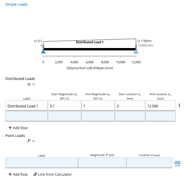
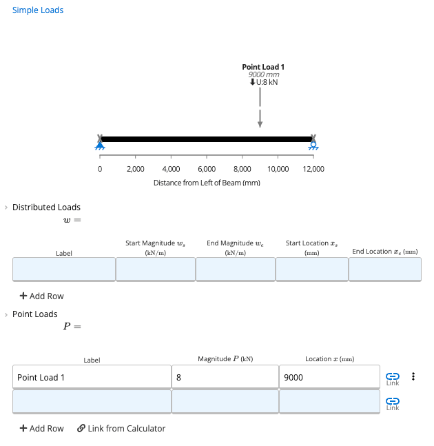
Simple Loads starts with a distributed load that runs from 0.1 to 1 kN/m over the full length. Clear that row. In Point Loads, add one load, Point Load 1, with a magnitude of 8 kN at a location of 9000 mm. The calculator applies the load as entered, with no load factor.Simple Loads section with the default Distributed Load 1 of 0.1 kilonewtons per meter at the start and 1 kilonewton per meter at the end, from 0 to 12 000 millimeters, and an empty Point Loads table.Simple Loads section with an empty Distributed Loads table and a Point Loads table with Point Load 1 of 8 kilonewtons at 9000 millimeters, and the beam diagram showing the load with a pinned support on the left and a roller on the right.
5

Read the summary

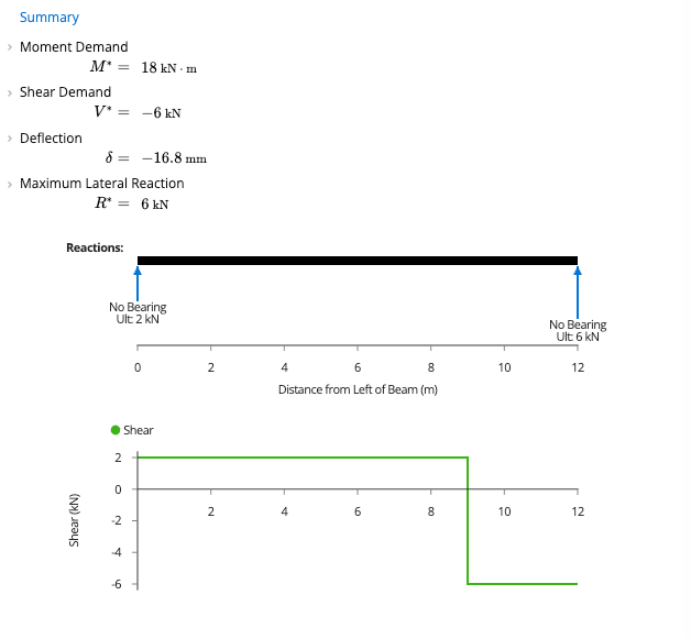
The Summary shows a Moment Demand M∗M^* of 18 kN·m, a Shear Demand V∗V^* of −6 kN, a Deflection δ\delta of −16.8 mm and a Maximum Lateral Reaction R∗R^* of 6 kN. The deflection is negative because the load acts downward. The reactions diagram shows 2 kN at the left support and 6 kN at the right.Summary with a Moment Demand of 18 kilonewton meters, a Shear Demand of minus 6 kilonewtons, a Deflection of minus 16.8 millimeters and a Maximum Lateral Reaction of 6 kilonewtons, a reactions diagram showing 2 kilonewtons at the left end and 6 kilonewtons at the right end, and the start of the shear graph.
6

Look at the graphs

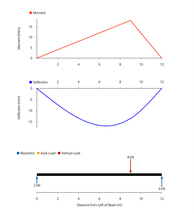
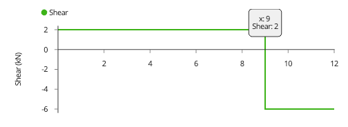
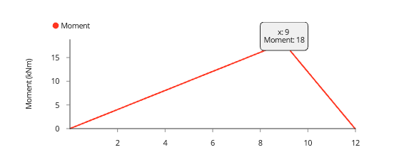
Below the Summary, the shear force steps from 2 kN to −6 kN at the load, the bending moment peaks at 18 kN·m at 9 m, and the deflection curve is lowest between the supports at about −16.8 mm. Hover over a point to read its value. The last diagram shows the 8 kN load and the reactions of 2 kN and 6 kN.Moment graph rising to a peak of 18 kilonewton meters at 9 meters, a deflection graph lowest at about minus 16.8 millimeters between the supports, and a diagram showing the 8 kilonewton load at 9 meters and reactions of 2 and 6 kilonewtons.Shear graph with a tooltip at x of 9 meters reading a shear of 2 kilonewtons, just before the step down to minus 6 kilonewtons.Moment graph with a tooltip at x of 9 meters reading a moment of 18 kilonewton meters.
7

Check the results per span and per support
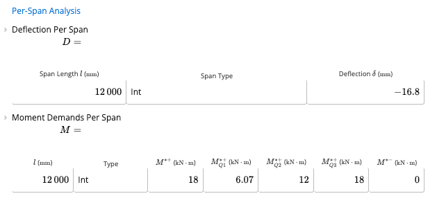
Per-Span Analysis lists one span of 12 000 mm with a deflection of −16.8 mm, a positive moment of 18 kN·m and a negative moment of 0. Per-Support Analysis lists reactions of 2 kN at 0 mm and 6 kN at 12 000 mm, with shears of 2 kN and −6 kN.Per-Span Analysis with a Deflection Per Span table showing a span length of 12 000 millimeters and a deflection of minus 16.8 millimeters, and a Moment Demands Per Span table with a positive moment of 18 kilonewton meters, values of 6.07, 12 and 18 at Q1, Q2 and Q3, and a negative moment of 0.Per-Support Analysis with a Support Demands Table giving reactions of 2 kilonewtons at 0 millimeters and 6 kilonewtons at 12 000 millimeters, and shears of 2 and minus 6 kilonewtons.
Inputs, Calcs.com output and a hand check

Inputs

CalculatorBeam Analysis
Length of beam LL12 000 mm
OrientationHorizontal
Left supportPinned at 0 mm
Right supportRoller at 12 000 mm
Bending stiffness EIEI12 000 kN·m²
EE200 GPa
II60 × 10⁶ mm⁴
Axial stiffness EAEA356 000
Point load PP8 kN
Load location9000 mm

Calcs.com output

Moment demand M∗M^*18 kN·m
Shear demand V∗V^*−6 kN
Deflection δ\delta−16.8 mm
Max lateral reaction R∗R^*6 kN
Reaction at 0 mm2 kN
Reaction at 12 000 mm6 kN

Hand check

✓Taking moments about each support, the right reaction is 8×9/12=8 \times 9 / 12 = 6 kN and the left reaction is 8×3/12=8 \times 3 / 12 = 2 kN
✓Shear: 2 kN left of the load and 2−8=2 - 8 = −6 kN right of it
✓Moment under the load: M=2×9=M = 2 \times 9 = 18 kN·m
✓EI=12 000EI = 12\,000 kN·m², from 200×106200 \times 10^6 kN/m² and 60×10−660 \times 10^{-6} m⁴. For a simply supported beam with one point load, the largest deflection is
δmax=P b (L2−b2)3/293 L EI\delta_{max} = \dfrac{P\,b\,(L^2 - b^2)^{3/2}}{9\sqrt{3}\,L\,EI},
where bb is the distance from the load to the nearer support (3 m). This gives
8×3×1353/293×12×12 000\dfrac{8 \times 3 \times 135^{3/2}}{9\sqrt{3} \times 12 \times 12\,000}
=0.0168= 0.0168 m, so 16.8 mm downward, at (L2−b2)/3=6.71\sqrt{(L^2 - b^2)/3} = 6.71 m from the left support

The reactions, shear, moment and deflection match the closed-form solution. The per-span and per-support tables are output from the calculator, with no hand check. This is a sanity check only. Beam Analysis version 63.

Method & scope

Symbols

These are the symbols used on this page, with the label the calculator shows where it has one.

Calculation method

The Beam Analysis calculator uses the finite element method (FEM) matrix stiffness approach to solve for internal forces, reactions, and deflections in simple or continuous beams.

FEA solver

The solver assembles the global stiffness matrix from member bending stiffness EIEI and axial stiffness EAEA, applies boundary conditions at each support, and solves the system {F}=[K]{u}\{F\} = [K]\{u\} for nodal displacements. Internal forces (moment, shear, axial) and deflections are then recovered from the displacement solution at a dense mesh of points along the beam length. The loads are not factored: the support reactions in the Summary equal the applied loads. For factored load combination analysis, use the Beam Analysis with Load Combinations (ASD) or (LRFD) calculators instead.

Reported results

The governing demand outputs are envelope maxima across the full beam. The moment demand across all spans is: M∗=max⁡(∣positive moment∣, ∣negative moment∣)\begin{aligned}M^* &= \max\bigl(\lvert\text{positive moment}\rvert,\\ &\qquad\ \lvert\text{negative moment}\rvert\bigr)\end{aligned} The shear demand and the deflection are taken across the beam length:
  • V∗=max⁡∣shear∣V^* = \max\lvert\text{shear}\rvert
  • δ=max⁡∣deflection∣\delta = \max\lvert\text{deflection}\rvert
Per-span analysis reports positive moment, Q1, midpoint, Q3, and negative moment peaks for each bay between supports. Per-support analysis reports the vertical reaction, moment reaction (for fixed supports), and shear at each bearing point.

Supported configurations

Supports can be fixed, pinned, roller, or spring (linear or rotational). Continuous rigid supports are also available. Beams can be horizontal or inclined (Simple Slope or Hip/Corner Slope). Loads include distributed (uniform or linearly varying), point loads, moment loads, and axial loads, at any position along the span.

How to use it

The sheet has Key Properties, optional spring and continuous supports, Simple Loads, a second group for axial, moment, linked and oriented loads, and Summary, Per-Span Analysis and Per-Support Analysis results. Clicking any input label opens a reference explanation for that field.
1

Enter the key properties

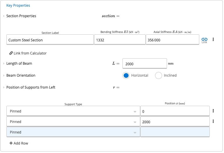
Key Properties starts with the Section Properties table. The calculator analyzes the beam from the section’s Bending Stiffness EIEI and Axial Stiffness EAEA, so the table asks for those two values.Key Properties section with a Section Properties table showing a section label, a Bending Stiffness EI of 1332 and an Axial Stiffness EA of 356 000, a Link icon, a Length of Beam of 2000 millimeters, Beam Orientation set to Horizontal, and a Position of Supports from Left table with two Pinned supports at 0 and 2000 millimeters.Enter the values manually, or link a section from one of the cross-section calculators.Entering the values manually: type EIEI and EAEA for the section into the table. The values can be entered as formulas. For example, for a standard steel beam with a second moment of area of 6 660 000 mm⁴, you could enter 200000 MPa * 6660000 mm^4.Linking a cross-section: a section can be linked from any of the cross-section calculators under Cross-Sections in Add New Calculation, such as the Cross-Section Database. See Look Up Section Properties in the Cross-Section Database.
  1. Add the cross-section calculator to the project and choose the section.
  2. In Beam Analysis, select the chain-link icon at the end of the Section Properties row.
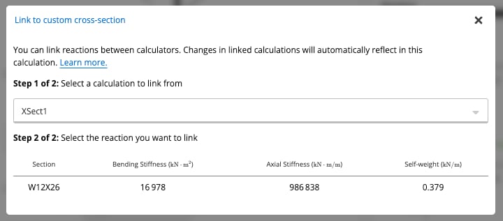
  3. In the Link to custom cross-section window, choose the calculation, then the section row. The window lists the section with its Bending Stiffness, Axial Stiffness and Self-weight. Link to custom cross-section window with a calculation selected and a table listing the section W12X26, with a Bending Stiffness of 16 978 kilonewton square meters, an Axial Stiffness of 986 838 and a Self-weight of 0.379 kilonewtons per meter.
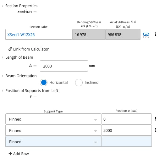
Once linked, the row shows the linked section’s label, EIEI and EAEA in grey, and the section drawing appears above the table.Section Properties row after linking, with the section label XSect1-W12X26, a Bending Stiffness EI of 16 978 and an Axial Stiffness EA of 986 838 shown in grey fields, followed by Length of Beam, Beam Orientation and the supports table.The calculator only analyzes the section for demands. It does not check the section against its capacity. Use a design calculator to design the member and check it against its capacity.Length of Beam is the total length from start to end, including any intermediate supports. Beam Orientation is Horizontal or Inclined.
2

Place the supports

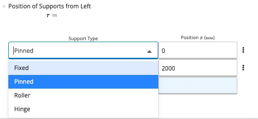
In Position of Supports from Left, choose a Support Type for each support and enter its Position (x), the distance from the left of the beam to the center of the support. Add as many supports as you need to make a continuous beam with any number of spans.Position of Supports from Left table with the Support Type list open, showing Fixed, Pinned, Roller and Hinge.A pinned support is fixed in translation and free in rotation. A fixed support is fixed in both translation and rotation.If the first support is not at 0, a cantilever is assumed at the left side. In the same way, if the last support is not at the end of the beam length, a cantilever is assumed at the end.The reactions at each support update automatically as supports are added, changed or deleted, based on the specified loading.
3

Add spring and continuous supports (optional)

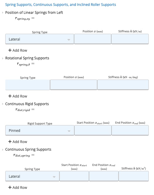
Open Spring Supports, Continuous Supports, and Inclined Roller Supports for four more tables.Spring Supports, Continuous Supports, and Inclined Roller Supports section with four tables: Position of Linear Springs from Left, Rotational Spring Supports, Continuous Rigid Supports and Continuous Spring Supports.
  • Position of Linear Springs from Left: a linear spring is either perpendicular to the beam (resisting lateral forces) or parallel to the beam (resisting axial forces). It acts equally in compression and tension. Enter the Spring Type, Position (x) and Stiffness (k). A spring support may not restrict the same degree of freedom as a rigid support, so a lateral spring cannot be added at the location of a pinned support.
  • Rotational Spring Supports: a rotational spring resists moments at a location, equally in either direction of rotation. A rotational spring cannot be added at the location of a fixed support.
  • Continuous Rigid Supports: a length of the span that is entirely prevented from moving in one or more directions. Choose a Rigid Support Type (Pinned or Roller) and enter the Start Position and End Position. Calcs.com models the continuous support as a series of closely spaced individual supports.
  • Continuous Spring Supports: a length of the span restricted by a linear spring. Choose a lateral or axial Spring Type, enter the Start Position and End Position, and enter the Stiffness (k). These are also modeled as a series of closely spaced spring supports.
4

Apply the simple loads

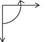
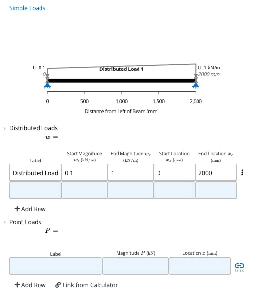
The calculator supports different loading types, which can be applied in combination. Each load can be named. The sign convention used for loading is (positive values shown):Loading sign convention diagram with an arrow pointing right, an arrow pointing down and a curved arrow in the corner between them.Simple Loads section with a beam diagram showing a sloping distributed load, a Distributed Loads table with one row of start and end magnitudes and locations, and an empty Point Loads table.Distributed Loads are in force per unit length, such as kN/m, along the beam. A distributed load starts and ends at any locations, and the start and end magnitudes may differ. Uniform loads have the same start and end magnitude. Linear loads have different start and end magnitudes, and can represent triangular or trapezoidal loads. All distributed loads entered in this table are applied perpendicular to the beam, whatever its orientation.Point Loads are in force units, such as kN, applied at one point along the beam. For example, a point load can represent a weight hung from a ceiling or a column supported by the beam. Enter the label, the magnitude and the location. All point loads entered in this table are applied perpendicular to the beam, whatever its orientation.To apply a load at an angle to the beam, use the tables in the next step.
5

Apply axial, moment, linked and oriented loads

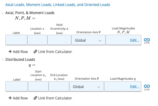
The second group has two tables: Axial, Point & Moment Loads, and Distributed Loads.Axial Loads, Moment Loads, Linked Loads, and Oriented Loads section with two tables: Axial, Point and Moment Loads with Location, Axial Eccentricity, Orientation Axis and Load Magnitudes columns, and Distributed Loads with Start Location, End Location, Orientation Axis and Load Magnitudes columns.
  • Axial, Point & Moment Loads are concentrated loads at a single point along the beam. Each row is one location. Axial eccentricity is the eccentricity at which the axial load is applied to the beam, so a non-zero eccentricity adds a moment equal to the axial load multiplied by the eccentricity.
  • Distributed Loads are applied along a continuous length of the beam. Each row is one pair of start and end locations.
  • Orientation Axis only matters if the beam is inclined. An Aligned orientation reads the inputs as exactly parallel and perpendicular to the beam. A Global orientation reads them along the global X and Y axes, which is useful because gravity always acts along the global Y axis however the beam is oriented.
Both tables have a Link from Calculator option.
6

Read the summary

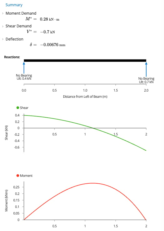
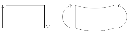
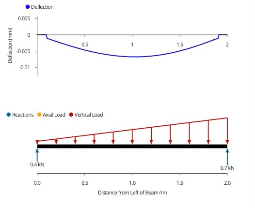
Once the section, supports and loads are entered, the calculator uses the Calcs.com finite element analysis engine to find the moments, shear forces and deflections. The Summary gives the maximum values as Moment Demand M∗M^* (the maximum of the positive and negative bending moments in the beam), Shear Demand V∗V^* and Deflection δ\delta, with the reactions on the beam.Summary section with a Moment Demand of 0.28 kilonewton meters, a Shear Demand of minus 0.7 kilonewtons, a Deflection of minus 0.00676 millimeters, and a beam diagram with a reaction labeled at each end.Below them are the shear force, bending moment and deflection diagrams along the beam, and a diagram of the loads and reactions. Hovering over any point on a diagram gives the value at that location along the beam. The sign convention used in the shear force and bending moment diagrams is (positive values shown):Sign convention diagram for shear force and bending moment, with a rectangle that has an upward arrow on its left side and a downward arrow on its right side, and a curved element with a curved arrow at each end.Shear, moment and deflection graphs below the Summary, followed by a load diagram showing a sloping distributed load and a reaction at each end.
7

Check the results per span and per support
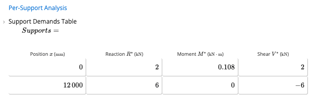
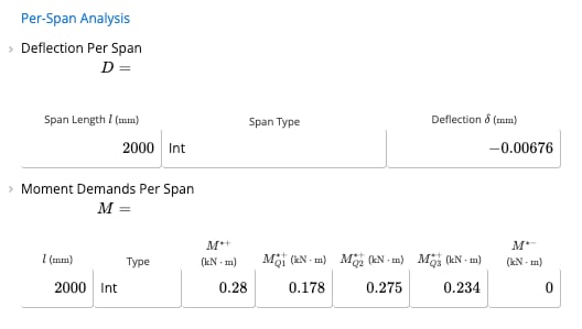
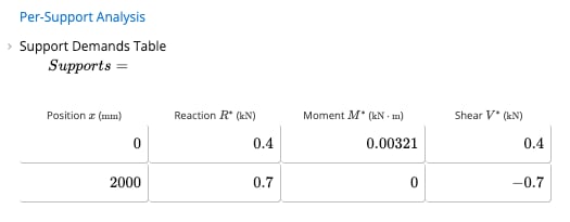
Per-Span Analysis and Per-Support Analysis list the results for each span and each support.Per-Span Analysis with a Deflection Per Span table giving span length, span type and deflection, and a Moment Demands Per Span table giving the positive moment, the values at Q1, Q2 and Q3, and the negative moment.Per-Support Analysis with a Support Demands Table giving the position, reaction, moment and shear at each support.

Beam Analysis with Load Combinations: Overview

This video covers the Beam Analysis with Load Combinations calculators (ASD and LRFD), and its examples use US units.
Timestamps are from the video captions and show roughly where each part begins.
0:00

Hello. In this short video, we’re going to look at our beam analysis with load combination calculator. So I’m gonna go and create this now. I’m gonna scroll down to the analysis section, and you can see we’ve got our beam analysis with load combinations ASD and LRFD. These are actually both the same behind the scenes they just use different load combinations. In this case we’re going to use ASD, but this would all be the same with the LRFD calculator.

0:25

So when I click on here you’ll see we’ve got quite a few different presets. These are all the same calculator behind the scene. They just have kind of different loads or different span lengths, things like that to represent their specific conditions. In this case, we’re just gonna stick with a generic beam. I’m gonna go and create this.

0:45

And if you’ve used our free beam calculator that’s available online, you’ll see that this is very similar to that. There are, however, quite a few differences that make this a lot more powerful, I think. The first one you’ll see here is the section properties. If you see we’ve got our section label, we can enter bending stiffness. So right now, we’ve got 29,000,000 psi times… So E times I, and then same with our axial stiffness. Now the axial stiffness doesn’t actually do much because we’re looking at a beam, so you don’t necessarily need to worry too much about that.

1:15

Where it gets really interesting is this link button. So if we click on this, you’ll see now that I’ve created a custom cross section. So if I look at it, I’ve got double channels here. I can select it, and all of a sudden, I’ve now linked my custom cross section to my analysis calculator. So now I’ll be able to check the deflections for that calculator, for that custom cross section.

1:40

So going down now, I’ve got my total beam length. So, obviously, this is the total length of our beam, including all of the spans. So if I’ve got multiple spans, I want the sum of all the span lengths. I can also change the incline to be a simple slope, so if I have a rafter design or if I have a hip corner slope. So basically, I have a valley or something like that, can also set that here. In this case, we’re just gonna stick to the horizontal.

2:04

I can also move my support. So say if I had a fixed support, I could add this here. I can also add hinges. So say if I have a hinge at… I’m just gonna make this up at three L over four, so at three quarters of the length. I could come here and add a hinge here. And as you can see now, we’ve got this. We can see our bending moment diagram, and that’s for this. If I say moved it to just L over four, this really has a drastic impact because there’s no moment through the hinge. Right?

2:37

So carrying on, I can enter loads in a myriad of ways here. So I can enter it in distributed loads in PSF. So I’ll enter the start location, end location, the tributary width at the start and at the end. The different tributary widths would be, for instance, if I have a triangular framing or floor, I could say have five at one end and two at the other end, and then have my trapezoidal load. And as I mentioned, I can also enter my load magnitudes in PSF. So here I’ve got twenty and forty.

3:11

I can also enter line loads. So again, these have start and end locations. So these you can see on the diagram. So if I start at say three feet and end at five feet, and I add a load magnitude, I can also have trapezoidal loads. So I can have, say, a 100 PLF at one end and 200 PLF at the other end. By default, if you see, it’ll just match to the… So that it’s the same load. But if I wanna override that, I can type in 200, and I’ve got my absolute load now.

3:44

I can also enter point loads. So if I just do this, and in that case, all I have to do is enter the load in pounds, or I can also enter moment loads in pound feet.

3:56

Carrying on, if I have, specific conditions for my live load, I may be able to reduce this to less than the design combination when it’s used in conjunction with other loads. So for instance, if I open the load combination analysis, I can see I’ve got my dead plus snow, but in some cases, I’ve got my dead plus live and snow. In some cases, I may be able to reduce the factor used on the live load here. So with that, that’s about all of the inputs for this calculator.

4:36

If we look at the outputs now, you will see that we show you the positive moment demand, negative moment demand, the shear demand, and maximum bearing. Now do keep in mind this is an analysis only calculator, so we don’t actually do the design checks on this. You’ll be able to do that in a separate calculator. But we also show you the deflections, and so these are calculated based on the actual cross section that you’ve linked or that you’re just choosing to design.

5:01

You’ll also see the reactions on the beam. You can also see our load combinations. And if we go to this tool here, we can select different load combinations. Let’s say if I wanna look at live and snow, I can see this, and there’s still the envelope that’ll show up to show the maximum. I can also see my free body diagram here.

5:23

If I wanted more detailed information, I can also go on the left here, and you can see, say, for unfactored loads. So my dead and my live, you can see have their specific shear moment for only those loads. And then I can still also see things for span. So I’ve got my short and long term deflection, my moment demands. I’ve also got my quarter moments in case I wanted to use this for a lateral torsional buckling analysis where I want my equivalent moment factor. And I can also look at loads per support, so seeing the reaction, the moment if it’s a fixed connection, and the shear at the support.

5:58

So that about concludes our video here. I hope this was helpful. As always, if you’ve got any questions, you can click on the blue help button at the bottom right. You’ll see some little articles here to help you, as well as an option to email us. We’re always happy to help as fast as we can. Thank you.

Common questions

Place the first or last support inward from the beam end. The overhang beyond the outermost support acts as a cantilever. The first support does not have to sit at 0, and the last does not have to sit at the full length.
Add a third support between the two ends. Three supports create two continuous spans, and the calculator solves the indeterminate reactions automatically.
A pinned support restrains translation but allows rotation. A fixed support restrains both. The Support Type list also has Roller and Hinge.
Yes. Use a Linear distributed load and set different start and end magnitudes. Equal start and end values give a uniform load instead.
No. It returns analysis demands (moment, shear, deflection). For capacity and code checks, send the results to the relevant design calculator, or see Link Design Calculators to Truss & Portal Frame Analysis.
Four steps: define the geometry, restrain it, load it, then read the demands. Set the span and the section stiffness (EIEI and EAEA). Place the supports, since their type and position decide whether the beam is determinate or continuous. Apply the point and distributed loads. The solver then returns the reactions, the shear force and bending moment diagrams and the deflected shape along the full length. For standard cases you can shortcut this with closed-form results, M=wL2/8M = wL^2 / 8 and δ=5wL4/384EI\delta = 5wL^4 / 384EI for a simply supported uniform load, but those only hold for textbook support and load arrangements. Anything continuous, cantilevered or unevenly loaded needs the general solution, which is why this calculator uses a finite element stiffness method instead.
FEA-based structural analysis of beams, no design code, no material selection required. It solves for bending moment, shear force, deflection, and support reactions at every point along the beam using a matrix stiffness method. The calculator handles simple spans, cantilevers, propped cantilevers, and multi-span continuous beams.
Beam length and bending stiffness EIEI (entered directly or linked from a section calculator), support types and positions (fixed, pinned, roller, hinge, spring), and applied loads, distributed (uniform or varying), point loads, moments, and axial loads. Inclined beam configurations are also supported.
Governing moment demand M∗M^* and shear demand V∗V^* (envelope maxima across the beam), maximum deflection, and support reactions (vertical, moment, and shear at each bearing). Per-span results include positive and negative moment peaks, and full diagrams for shear force, bending moment, deflection, and free-body are generated.
Yes, it supports any combination of fixed, pinned, roller, hinge, and spring supports. Cantilever overhangs, propped cantilevers, and multi-span continuous configurations with any support layout are all handled by the FEA solver.
The governing M∗M^* and V∗V^* values feed directly into wood, steel, or concrete beam design calculators. You can link the support reactions from this analysis directly to a column or footing calculator in the same Calcs.com project so the design chain stays connected.
Yes, support reactions link directly to connected column or footing calculations in the same project. When any load or geometry input changes in this beam analysis, all linked downstream calculations update automatically, no manual re-entry of reactions.

Next steps

Use the Beam Analysis with Load Cases Calculator

Analyze simple and continuous beams under AS/NZS 1170.0:2002 (Amdt 5) load combinations, with governing demands identified by load case.

Use the Beam Analysis with Load Combinations (ASD) Calculator

Analyze beams to ASD load combinations per IBC 2009-2024 and ASCE 7-10 to 7-22. Enter unfactored loads for governing moment, shear and deflection.

Use the Beam Analysis with Load Combinations (LRFD) Calculator

Analyze beams to LRFD load combinations per IBC 2009-2024 and ASCE 7-10 to 7-22. Enter unfactored loads for governing factored Mu and Vu.