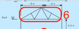
Building Geometry
The below example has closely followed the dimensions and loading of SCI P387 (see reference below). The resulting member demand and capacity can therefore be verified between the 2 sources! Steel Building Design: Worked examples for students © 2009 The Steel Construction Institute P387. Find at SteelSCI.com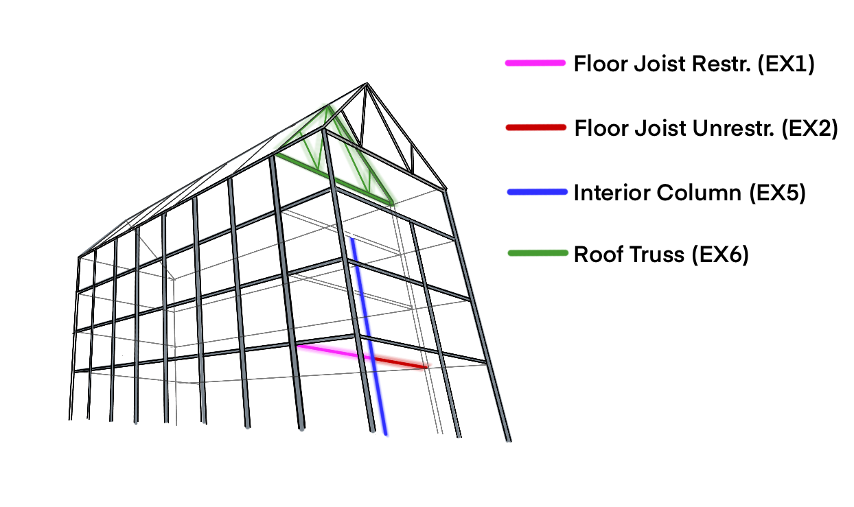
- Project Defaults: Set Default Loadings, Deflection Limits & Load Combinations
- Steel Beam and Steel Column Calculators EX 1, 2, 5 & 6 (design only)
- Truss Calculator EX 6
- Load Linking (see 24-linking-reactions-between-beams-and-columns-load-path-tracking for further details)
How was this Project Created?
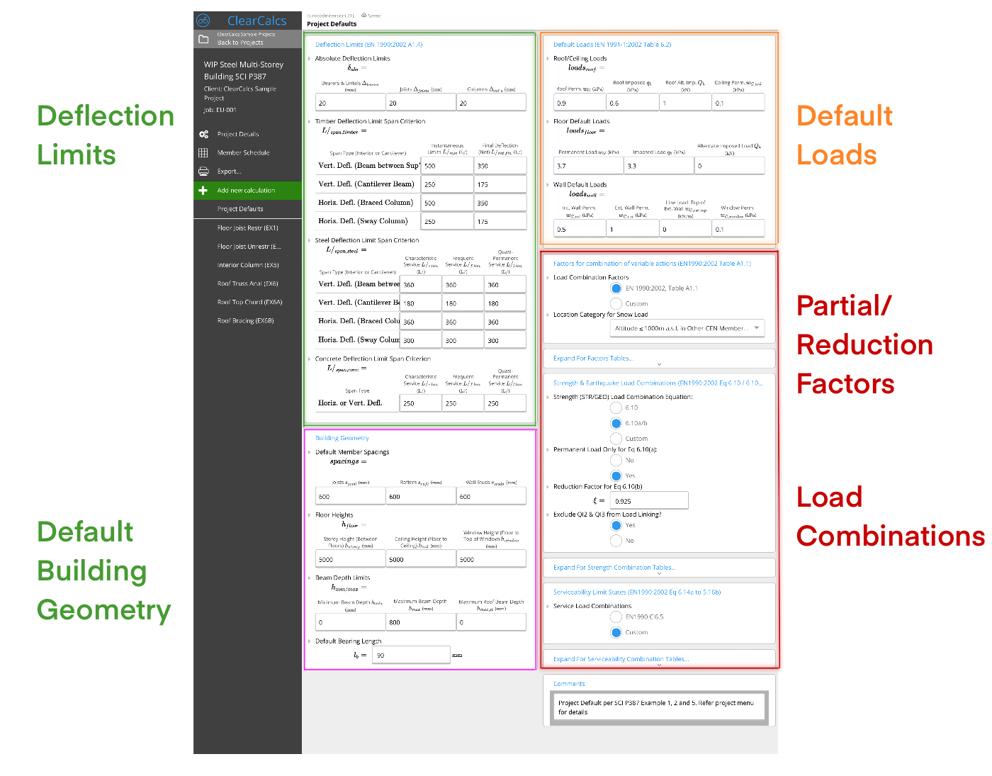
Creating the Project Defaults Page:
The Project Defaults are provided for users to input for EN 1990/1991 - Basis of Structural Design and Loading which will be used throughout the project, as well as any National Annex specific settings. For further details see 176-project-defaults-eu. The project specific settings used for this example include:-
Partial/Reduction Factors & Combinations of Actions - See SCI P387 Cl 3.2.1.
- Partial / Reduction Factors - Use Calcs.com Defaults
- Strength Combination of Action - UK NA requires the use of Eqs 6.10 a/b load combinations and a Reduction Factor ξ = 0.925.
- Serviceability Combinations - UK NA does not consider Dead Load in Serviceability Load Combinations. Select “Custom” and amend Dead Load factors.
-
Deflection Limits - See SCI P387 Cl 3.2.2.
- Steel Deflection Limits - use Calcs.com provided defaults (consistent with UK for characteristic but we override frequent and quasi-permanent to* Span / 1 (i.e. no checks required per UK NA.2.23)*
- Absolute deflection limits - not used in SCI P387 (in a usual case deflection is limited by plaster or other building restrictions), so we arbitrarily increase this to 100mm.
- Timber / concrete deflection limits - leave as blank as they are not used in this project.
-
Default Loads - See individual examples.
- Floor Default Loads - Floor Joists Example 1 & 2 use a floor self-weight of 3.7 kPa, and an imposed floor load of 3.3 kPa.
- Roof / Wall Default Loads - These are not used in this project, so are left as is.
-
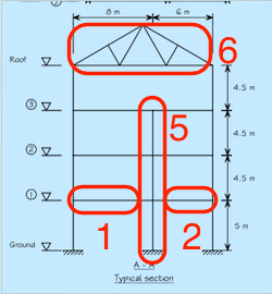
Default Building Geometry -
- Floor Heights - set to 5000mm, as used in SCI P387. For the single column calculation being completed here, this only provides marginal time saving, however in reality there would be a number of columns with different geometry and loading.
Creating the Joist Calculators (EX1 & 2)
 Feature Preview
Pro Tip 1: Because we added Default Loads & Default Load Widths in Project Defaults, these loads are now automatically applied to each Floor Joist calculator as Distributed Loads with load widths!
Pro Tip 2: Because we added Load Combinations and Factors in Project Defaults, these combinations are now checked for each joist calculator. You can even see the force and deflection graphs for each of these combinations!
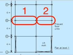
A typical “restrained” and “unrestrained” floor joist has been analysed and designed by Calcs.com mirroring the SCI P387 calculation procedure. For further details on Joist Calculator see 173-how-to-design-a-steel-beam-to-en1993. The “Floor Joist” sub-category was selected to ensure default loading would be transferred. The following data was entered:
Feature Preview
Pro Tip 1: Because we added Default Loads & Default Load Widths in Project Defaults, these loads are now automatically applied to each Floor Joist calculator as Distributed Loads with load widths!
Pro Tip 2: Because we added Load Combinations and Factors in Project Defaults, these combinations are now checked for each joist calculator. You can even see the force and deflection graphs for each of these combinations!
A typical “restrained” and “unrestrained” floor joist has been analysed and designed by Calcs.com mirroring the SCI P387 calculation procedure. For further details on Joist Calculator see 173-how-to-design-a-steel-beam-to-en1993. The “Floor Joist” sub-category was selected to ensure default loading would be transferred. The following data was entered:
-
Geometry and Steel Grade Inputs -
- Steel Grades - For EX1, select EN 10025-2 UK Prod Std, Gr. S275 (3mm < t <= 16mm) and for EX 2 (16mm < t <= 40mm). Calcs.com also provides simplified grades per EN1993, although the UK NA does not allow using these.
- Length Between Lateral Restraints - set to 0 for full restraint (EX1) and 6000 mm for the unrestrained joist (EX 2)
- Pinned Supports - added at each end of the beam.
-
Loads (EN 1991)
- Because we added Default Loads in Project Defaults, these are now automatically applied to each Floor Joist calculator!
- Self-weight - set to “No” for Restrained Beam (EX1). Set to “Yes” for Unrestrained Beam (EX2) and an additional 1.78 kN/m dead load to equal a total strength UDL = 60.8kNm per SCI P387.
- Building Category - set to Category “B: Office Areas”
- We don’t change any of the other defaults, loading is applied through shear centre, and loaded from top.
- Design Criteria - all deflection limits are taken from Project Defaults.
-
ULS: Buckling Resistance of Uniform Member in Bending (EN 1993-1-1:2005 Cl 6.3.2) - EX 2 only
- Equivalent uniform moment factor C1 - set to 1.13 consistent with SCI P387.
- C2 and k - leave as is.
Creating the Column Calculator (EX5)
Pro Tip 1: W e can now link the reactions from the joists on each side of the column at each floor. (see 24-linking-reactions-between-beams-and-columns-load-path-tracking for further details). Pro Tip 2: Because we added a storey height in Project Defaults, we can now use this to set both the total column height and distance between lateral restraints. This also shows off using Calcs.com’s custom user formulas, where you can do arithmetic, units and more within any input field. (see 113-how-to-use-formulas-and-convert-units-in-inputs for further details). The interior column connecting each floor (excluding the roof) is designed by Calcs.com mirroring the SCI P387 calculation procedure. For further details on the Column Calculator see 174-how-to-design-a-steel-column-to-en1993. The following data was entered:-
Geometry and Steel Grade Inputs -
- Steel Grades - Select EN 10025-2 UK Prod Std, Gr. S275 (3mm < t <= 16mm) as per steel joists above.
- Total Column Height - set to projectDefault(“h_storey”) * 3Here we use our storey height project defaults and use a custom user formulas as per the Pro Tip above to find the height of 3 storeys combined.
- Critical Buckling Lengths - set to projectDefault(“h_storey”) which represents the distance between each floor restraint
- Position of Support from Bottom - Fixed support added at bottom of column. The floors do not provide lateral restraint.
-
Loads (EN 1991)
- Axial, Lateral & Moment Loads - We now link reactions from floor joists (EX1 & EX2) to each storey of the column. Note that you can link each reaction multiple times, as the joists in each storey carry the same load.
- Default Axial Load Eccentricity - Set “Y-axis face” eccentricity, which by default applies the eccentricity at 100mm from the face of the flange, consistent with SCI P387. Only Level 1 moment is checked. Because the ratio of column stiffnesses < 1.5, the design moment due to eccentricity is reduced by half, achieved by halving eccentricity Axial Eccentricity = e_y/2 . E.g.
- Building Category - set to Category “B: Office Areas” exactly as for the steel joists.
- Self-weight - set to “No”
-
Design Criteria & National Annex Parameters
- all deflection limits are taken from Project Defaults.
- leave partial factors & factor for shear area per the Default values.
- Buckling Interaction - set to Annex A (less conservative and recommended by UK National Annex)
-
ULS: Buckling Resistance of Uniform Member in Bending (EN 1993-1-1:2005 Cl 6.3.2)
- Equivalent uniform moment factor C1 & C2- leave as 1 & 2 respectively consistent with SCI P387
Creating the Truss Analysis Calculator (EX6)
 Pro Tip 1: The truss analysis calculator can accept any arbitrary truss dimensions by choosing a “Custom Truss” and entering nodes and elements manually.
Pro Tip 2: Any member from the truss analysis calculator may be designed within our column calculator . In future the results and dimensions of the member may be directly linked to the design calculator to prevent duplicating data!
The roof truss spanning between exterior columns has been modelled below. See 151-how-to-use-the-truss-analysis-wizard for further details.
Pro Tip 1: The truss analysis calculator can accept any arbitrary truss dimensions by choosing a “Custom Truss” and entering nodes and elements manually.
Pro Tip 2: Any member from the truss analysis calculator may be designed within our column calculator . In future the results and dimensions of the member may be directly linked to the design calculator to prevent duplicating data!
The roof truss spanning between exterior columns has been modelled below. See 151-how-to-use-the-truss-analysis-wizard for further details.
-
Truss Geometry
- Truss Type: set to Custom Truss. The shape of the roof truss is similar to a “simple fink truss” (see types here 152-truss-types) however the spacing of bracing is slightly different so custom dimensions have been entered.
-
Member Selection -
- Chord / Web Members - Select 100 x 100 x 5 SHS for chords & 70 x 70 x 5 SHS for bracing members. The steel grade is not entered here as it doesn’t affect the deflection / forces in the structure.
-
Nodes, Elements & Supports
- Nodes - Enter the global x and y coordinate of each node of the truss (in any order
- Elements - Enter the member and its type (i.e. 1- Top Chord, 2- Web Member, 3- Botttom Chord)
- Supports - Enter a Pinned & Roller (Y restrained) at the start & end nodes to model a simply supported truss.
-
Loads (EN 1991)
- Include Self-Weight - set to “Yes” as the total combined actions value of 7.32 kN/m does not include the SHS self-weight.
- FEA Point Loads - set to Fd = 43.92 kN at all intermediate nodes, and half of Fd at each support node consistent with SCI P387. Orientation is set to the global value (-90deg = vertical). Labels are not used