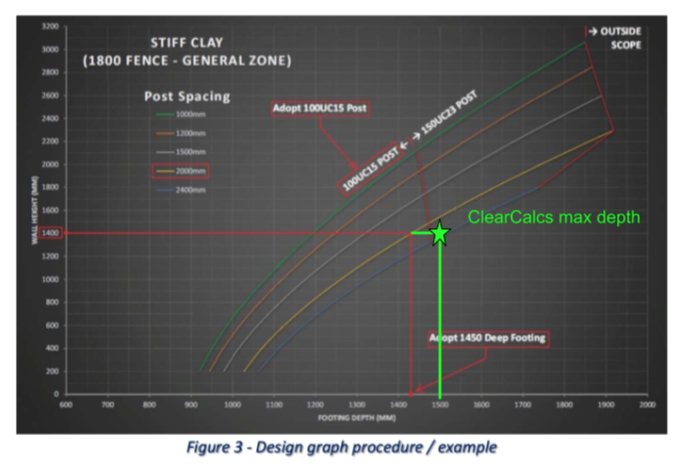
Example 1 - 1.4m retained height & 2m spacing of posts
Reference: Tuff Ozzy Concrete Sleepers Technical Design Guide Rev A - Mar 2020 **Section 4.0 (**link: TUFF-OZY-TECHNICAL-DESIGN-GUIDE2.pdf) Tuff Ozzy Design guide covers a range of typical sleeper retaining walls. A deemed-to-comply size and spacing of posts is given, without specific details on moment or shear demand/capacity. Deflection Limits are assumed not to be checked in Tuff Ozzy, which Calcs.com provides additionally. The advice is based on typical retaining wall applications in QLD.1. Inputs
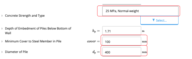
1.1 Pile/Steel Post Inputs
1.2 Wind Inputs
** Wind Classification is not given in Tuff Ozzy Design Guide, however is derived per below for No Shielding = NS, and flat terrain (Topographic Class = T1)

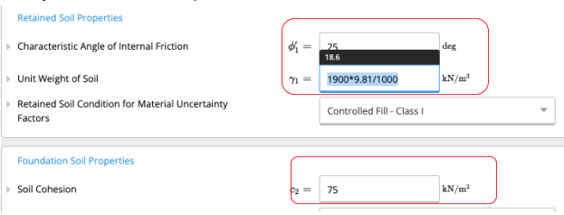
 1.3 Soil Inputs
Tuff Ozzy Design Manual assumes same soil parameters for retained and foundation soil.

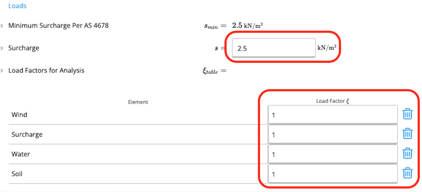
1.4 Loading
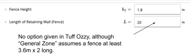
1.5 Fence
1.6 Limitations
- SEC 2.2 Sleeper retaining walls within this brochure are not permitted to be installed within 1km of the coastline, or a large body of salt water.
- SEC 2.4 ‐ General Zone: A maximum 1800 high fence that is further than 3.6m away from a free end may be installed on top of the wall. Fence posts located within this ‘general zone’ are subjected to only half the wind pressure of those within the ‘end zone’
- SEC 2.4 - Please note that this design guide does not cover fences within cyclonic areas.
- SEC 2.8.3 - The design graphs in section 5.0 of this brochure have made no allowance for a battered backfill (refer Figure 4 in section 5.0).
2. Outputs
Tuff Ozzy Design Manual provides a deemed-to-comply chart output. Calcs.com results are therefore plotted on the same chart. The results are slightly more conservative in Calcs.com (within 10%). If more typical surcharge load / soil load factors are assumed, Calcs.com would be additionally conservative compared to Tuff Ozzy Design Manual.