

- Key Properties
- Design Criteria
- Loads
- Summary and Graphs
1. Key Properties
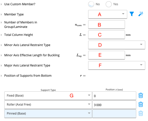
A. Member Type
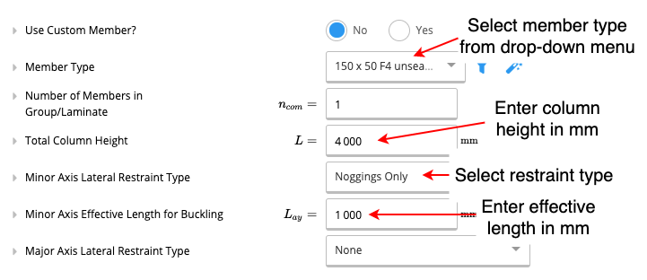
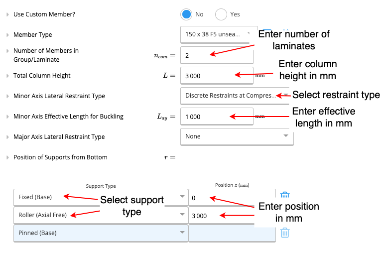
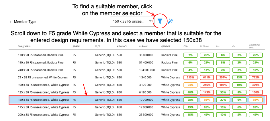
Calcs.com gives the user the opportunity to use a custom member size if they wish. If ‘no’ is selected for the use of custom members, the user is provided with a drop-down list industry-standard size members from which a member can be selected.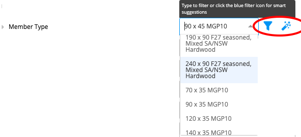 Alternatively, the member selector and autosize functions (circled in red in the above diagram) can also be used to select a member.
B. Number of Members in Group/Laminate
The number of timber laminates in the column. This quantity needs to be either equal to or greater than 1.C. Total Column Height
The total height of the column needs to be given In millimetres (mm).D. Minor Axis Lateral Restraint Type
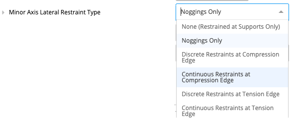 A drop-down menu is provided to specify the type of lateral restraint present along the minor axis of the column.
E. Minor Axis Effective Length for Buckling
If a discrete lateral restraint type is present along the minor axis of the column, the calculator will ask for the effective length along the minor axis. This is the greatest distance between two subsequent lateral restraints and it must be specified in millimetres (mm).F. Major Axis Lateral Restraint Type
 A drop-down menu is provided to specify the type of lateral restraint present along the major axis of the column. If ‘discrete’ lateral restraints are used, the calculator will prompt the user to enter the major axis effective length for buckling in millimetres (mm).
G. Position of Supports From Bottom
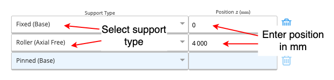
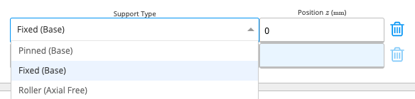 This section prompts the user to select the support type from a drop-down menu and then specify the location of each support in millimetres(mm) as measured from the bottom of the column.
2. Design Criteria
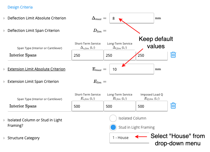
Deflection Limit Absolute Criterion: This is the hard maximum deflection allowed for the column, regardless of span length, and applied to all load cases. Extension Limit Absolute Criterion: This is the hard maximum extension allowed for the column.3. Loads
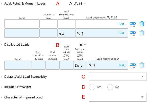
A. Axial, Point & Moment Loads
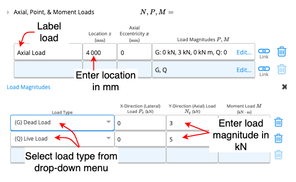
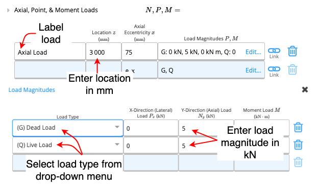
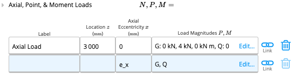 To enter an axial, point or moment load, one needs to fill out the above table. The first column refers to the name of the load, which can be decided by the user. Then the location at which the load acts on the column as measured from the bottom of the column (in millimetres) needs to be entered. The third column refers to the axial eccentricity of the load; this is set according to the “Default Axial Load Eccentricity” by default. Axial eccentricity will be discussed in detail in part C of this section. When one clicks on the fourth column the following table will appear.
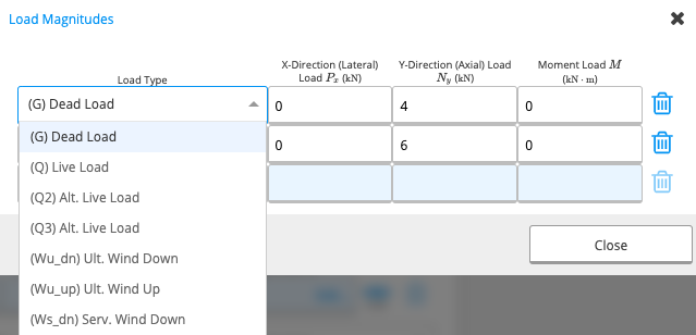 In this table, the user can select the load type from the drop-down menu shown, and specify the magnitude of the load in the x and y directions in kilo Newtons(kN) and enter any moment loads in kilo Newton Metres(kNm).
B. Lateral Distributed Loads
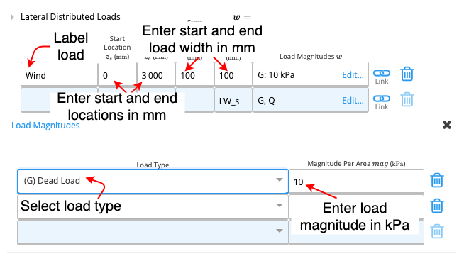
 This table is applicable to distributed loads that act in the x-direction (i.e. perpendicular to the column). Similar to the Point Loads table, the first column of the lateral distributed loads table prompts the user to name the load. Then the start and end location of the distributed load must be specified, as measured from the bottom of the column. Then the start and end width of the load must be entered in millimetres(mm). To enter the load magnitudes, the following table must be filled out.
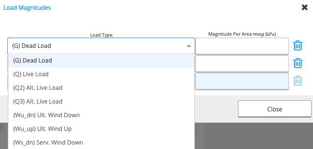 The load type must be selected from the drop-down menu in the first column, then the load magnitude must be specified per area in units of kilo Pascals(kPa).
C. Default Axial Load Eccentricity
What is Axial Load Eccentricity? Generally, axial loads (i.e. loads acting vertically downwards) act through the centre of a column. However, in some cases, the load can act off the centre of the column and cause bending in addition to compression of the column. Axial load eccentricity refers to the horizontal distance between the centre of the column and the line of action of the axial load. Axial Load Eccentricity Options in Calcs.com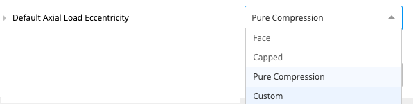
- ‘Face’ assumes default eccentricity to be the face of the member plus a 100mm
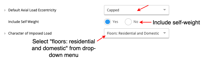
- ‘Capped’ assumes default eccentricity to be equal to the face of the member
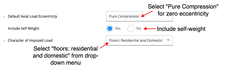
- ‘Pure Compression’ assumes zero eccentricity. The calculator is set to pure compression by default.
- ‘Custom’ allows the user to specify the default eccentricity as needed.
D. Include Self-Weight
The user can choose whether or not they include the self-weight of the column in their calculations. The calculator is set to include the self-weight by default unless the user specifies otherwise.E. Character of Imposed Load
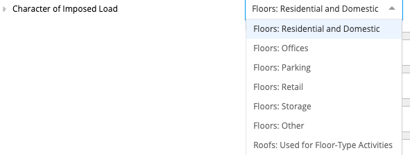 The character of imposed loads that is most applicable to the applied imposed loads (live loads) on the column can be selected from this drop-down menu.
4. Summary & Graphs
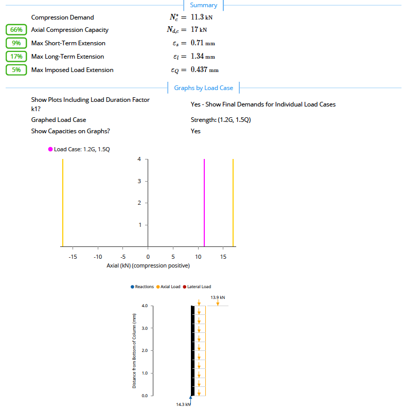
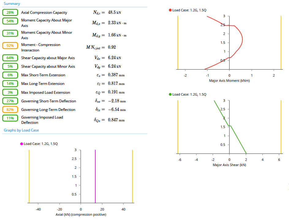
The summary section the key parameters of your calculation will be outlined. In the graphs section, the user can select whether or not they include the load duration factor k1 in the plots and select the load case that they would like the see in their graph (e.g.: 1.2G 1.5Q). The user can also specify whether they want the axial compression capacity graphed on the plot. A sample of the summary and graphs produced during calculations can be seen in the examples given below.Examples
Task 1
Design a timber stud with the following characteristics- for residential application
- 4m in height with noggings (along the minor axis) every 1m
- member type: 150x50 F4 White Cypress
- fixed base and a roller support at the top
- an axial load at the top: 5kN/m dead load and 8.3kN/m live load with 600mm stud spacing
- assume zero eccentricity
- include self-weight
Method
 Summary & Graphs
 Access the full PDF file here: Task 1
Task 2
Design a timber column with the following characteristics- for residential application
- 5m in height and discrete restraints halfway at the compression edge along the minor axis
- fixed support at the bottom and roller support at the top
- 2 laminates
- Assume default load eccentricity to be equal to be the face of the member
- Axial load at the top of 5kN each of dead load and live load
- A laterally distributed wind load of 10kPa from top to bottom of the column (load width 100mm)
- include self-weight
- select an F5 grade unseasoned White Cypress Member that meets the design demands
Method
 Summary & Graphs
 Access the full PDF file here: Task 2