> ## Documentation Index
> Fetch the complete documentation index at: https://calcs.com/docs/llms.txt
> Use this file to discover all available pages before exploring further.
# How to Enter Distributed Loads (Imperial Units)
> How to Enter Distributed Loads (Imperial Units)
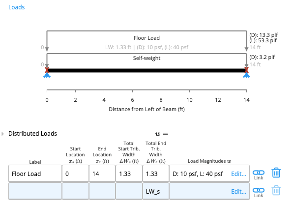
In Calcs.com there is a designated table for Distributed Loads under the Loads section. This table is accompanied by a diagram of the structural component that is being analysed, which updates in real-time and indicates the loads you have entered.
 This article will discuss the input parameters in the Distributed Loads table and gives some worked examples on how to input distributed loads into Calcs.com for structural design applications.
# Input Parameters
This article will discuss the input parameters in the Distributed Loads table and gives some worked examples on how to input distributed loads into Calcs.com for structural design applications.
# Input Parameters
 | Parameter | Description |
| :-------------------------- | :-------------------------------------------------------------------------------------------------------------------------------------------------------- |
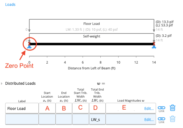
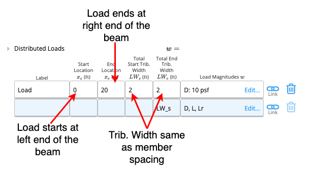
| **Start Location (A)** | The distance from the left end (zero point) of the beam where the load begins. Measured in feet. |
| **End Location (B)** | The point where the load ceases to act, measured from the left end (zero point) of the beam. Measured in feet. Use **'L'** for the right end of the beam. |
| **Tributary Width (C & D)** | The width of the area from which the member obtains its load. See the explanation below for details. |
| **Load Magnitude (E)** | The pressure magnitude, entered in Pounds per Square Foot (PSF). Click the cell to open a table where you can select the load type and enter the value. |
**Pro Tip:** You can enter conversion formulas directly into the cell (similar to Excel) for both Start and End locations.
**Shortcut:** If the end location is the right end of the beam, you can input **'L'** instead of the actual length value.
## Understanding Tributary Width
Every structural element has an area from which it obtains its load. As with any other area, this can also be expressed as a product of length and width. The length of this area is usually either the length of the element itself or the length of the distributed load (B-A from the table). Tributary width is simply the width of this area.
To better illustrate this concept, consider a floor that is supported by members spaced 's' ft apart.
| Parameter | Description |
| :-------------------------- | :-------------------------------------------------------------------------------------------------------------------------------------------------------- |
| **Start Location (A)** | The distance from the left end (zero point) of the beam where the load begins. Measured in feet. |
| **End Location (B)** | The point where the load ceases to act, measured from the left end (zero point) of the beam. Measured in feet. Use **'L'** for the right end of the beam. |
| **Tributary Width (C & D)** | The width of the area from which the member obtains its load. See the explanation below for details. |
| **Load Magnitude (E)** | The pressure magnitude, entered in Pounds per Square Foot (PSF). Click the cell to open a table where you can select the load type and enter the value. |
**Pro Tip:** You can enter conversion formulas directly into the cell (similar to Excel) for both Start and End locations.
**Shortcut:** If the end location is the right end of the beam, you can input **'L'** instead of the actual length value.
## Understanding Tributary Width
Every structural element has an area from which it obtains its load. As with any other area, this can also be expressed as a product of length and width. The length of this area is usually either the length of the element itself or the length of the distributed load (B-A from the table). Tributary width is simply the width of this area.
To better illustrate this concept, consider a floor that is supported by members spaced 's' ft apart.
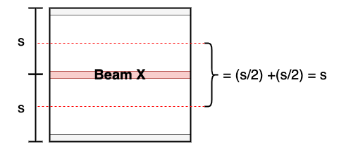 **Key Concept:** For most cases, the tributary width is the same as member spacing.
Consider beam X, where its tributary area has the same length as the beam and the tributary width is 's'. Notice that the tributary area is not always a rectangle and can instead take on a triangular shape. In such instances:
* The starting and ending tributary widths will be different
* You'll need to enter different values for **Total Start Tributary Width** and **Total End Tributary Width**
Both tributary width values are measured in feet and refer to the width of the tributary area at the starting and ending points of the distributed load, respectively.
## Load Magnitudes
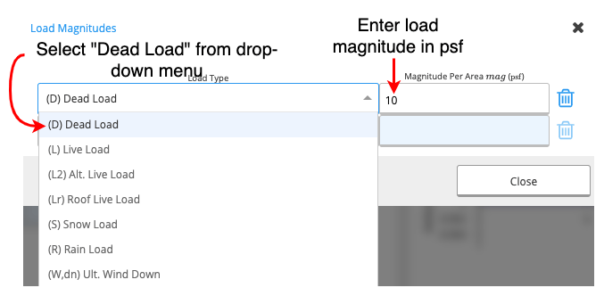
When you click on the Load Magnitudes cell, a new table will appear (see below).
**Key Concept:** For most cases, the tributary width is the same as member spacing.
Consider beam X, where its tributary area has the same length as the beam and the tributary width is 's'. Notice that the tributary area is not always a rectangle and can instead take on a triangular shape. In such instances:
* The starting and ending tributary widths will be different
* You'll need to enter different values for **Total Start Tributary Width** and **Total End Tributary Width**
Both tributary width values are measured in feet and refer to the width of the tributary area at the starting and ending points of the distributed load, respectively.
## Load Magnitudes
When you click on the Load Magnitudes cell, a new table will appear (see below).
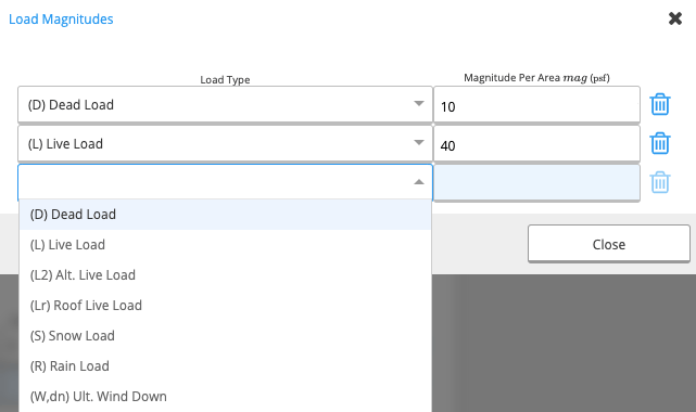 * **First Column:** A drop-down menu from which you can choose your load type.
* **Second Column:** You can input the magnitude of the load in Pounds per Square Foot (PSF).
# Examples
## Example 1
### Task
Input a live load of 40psf on a floor joist with a member spacing of 1.33ft.
### Method
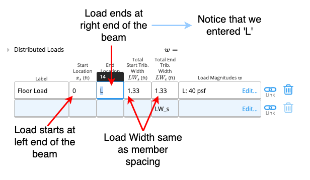
Enter **0** for Start Location and **L** for End Location to apply the load to the full beam.
Input the member spacing (**1.33ft**) into both the Start and End Tributary Width cells.
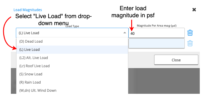
Click the **Load Magnitudes** cell, select **Live Load** from the dropdown, and enter **40** in the magnitude field.
* **First Column:** A drop-down menu from which you can choose your load type.
* **Second Column:** You can input the magnitude of the load in Pounds per Square Foot (PSF).
# Examples
## Example 1
### Task
Input a live load of 40psf on a floor joist with a member spacing of 1.33ft.
### Method
Enter **0** for Start Location and **L** for End Location to apply the load to the full beam.
Input the member spacing (**1.33ft**) into both the Start and End Tributary Width cells.
Click the **Load Magnitudes** cell, select **Live Load** from the dropdown, and enter **40** in the magnitude field.
 ## Example 2
### Task
Input a dead load of 10psf on a ceiling joist with a member spacing of 2ft.
### Method
Enter **0** for Start Location and **L** for End Location to apply the load to the full beam.
Input the member spacing (**2ft**) into both the Start and End Tributary Width cells.
Click the **Load Magnitudes** cell, select **Dead Load** from the dropdown, and enter **10** in the magnitude field.
## Example 2
### Task
Input a dead load of 10psf on a ceiling joist with a member spacing of 2ft.
### Method
Enter **0** for Start Location and **L** for End Location to apply the load to the full beam.
Input the member spacing (**2ft**) into both the Start and End Tributary Width cells.
Click the **Load Magnitudes** cell, select **Dead Load** from the dropdown, and enter **10** in the magnitude field.
 ## Example 3
### Task
Input a roof live load of 20psf and a dead load of 15psf on a rafter with 1.33ft member spacing.
In the calculator for rafters, you will notice that there's an additional column in the distributed loads table (as shown in the image below).
## Example 3
### Task
Input a roof live load of 20psf and a dead load of 15psf on a rafter with 1.33ft member spacing.
In the calculator for rafters, you will notice that there's an additional column in the distributed loads table (as shown in the image below).
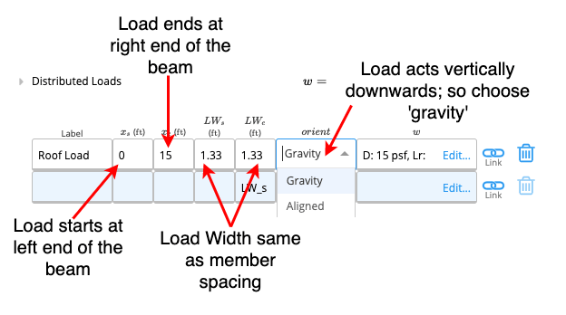
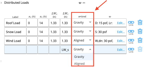 This column refers to the orientation of the line of action of the specified load. There is a drop-down menu from which you can choose either gravity or allied.
* **Gravity:** The load always acts vertically downwards. e.g. weight force
* **Allied:** The load acts perpendicular to the surface of the structural element. e.g. wind
### Method
Enter **0** for Start Location and **L** for End Location to apply the load to the full beam.
Input the member spacing (**1.33ft**) into both the Start and End Tributary Width cells.
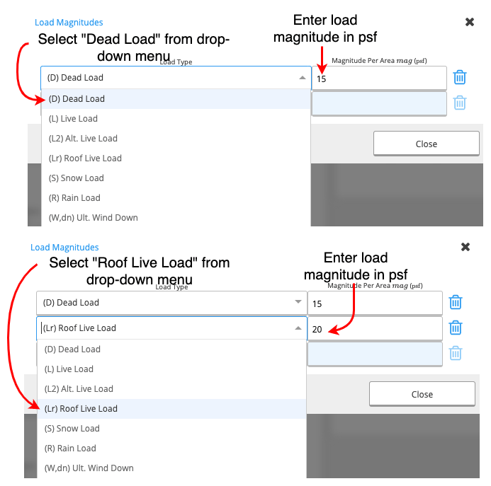
Click the **Load Magnitudes** cell to open the load table. Add two rows:
* Select **Roof Live Load** and enter **20** in the magnitude field
* Select **Dead Load** and enter **15** in the magnitude field
This column refers to the orientation of the line of action of the specified load. There is a drop-down menu from which you can choose either gravity or allied.
* **Gravity:** The load always acts vertically downwards. e.g. weight force
* **Allied:** The load acts perpendicular to the surface of the structural element. e.g. wind
### Method
Enter **0** for Start Location and **L** for End Location to apply the load to the full beam.
Input the member spacing (**1.33ft**) into both the Start and End Tributary Width cells.
Click the **Load Magnitudes** cell to open the load table. Add two rows:
* Select **Roof Live Load** and enter **20** in the magnitude field
* Select **Dead Load** and enter **15** in the magnitude field