


- Key Properties
- Loads
- Design Conditions
- Summary and Graphs
Worked example
Example 1: simply supported beam
A simply supported glulam beam spans 4 m under a dead load of 10 kN/m and a live load of 15 kN/m. The steps below use the conditions in the image.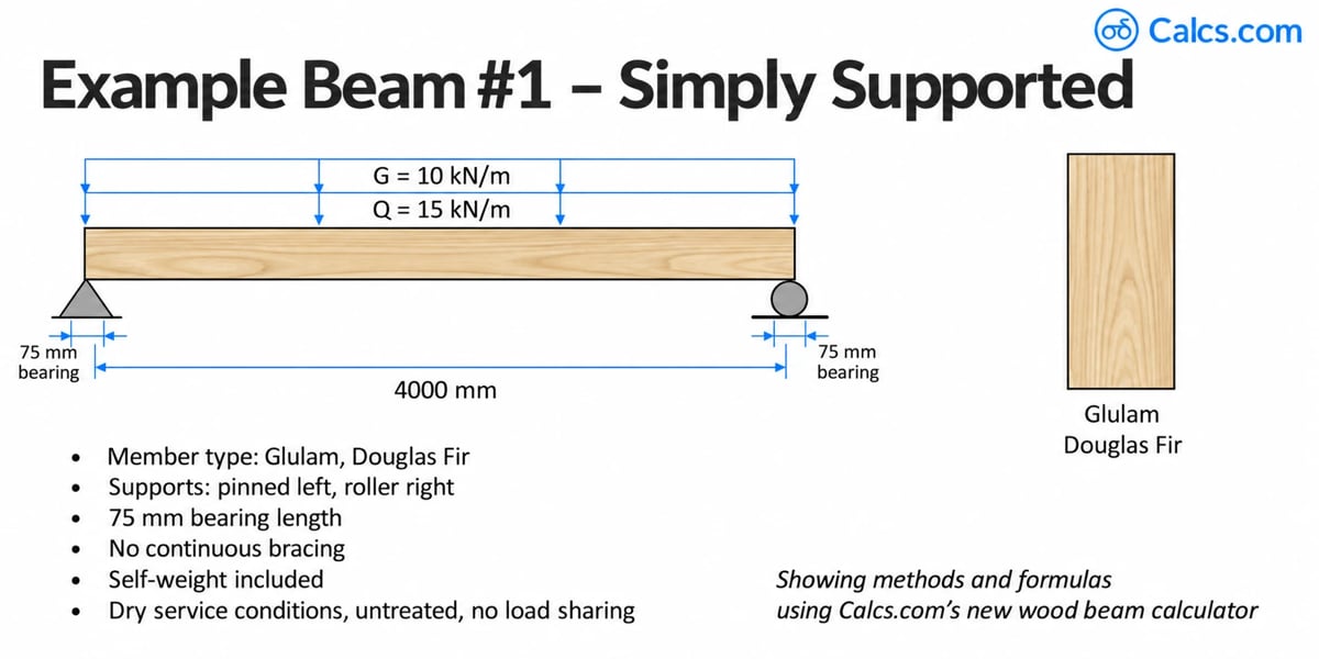
- Length: 4 meters
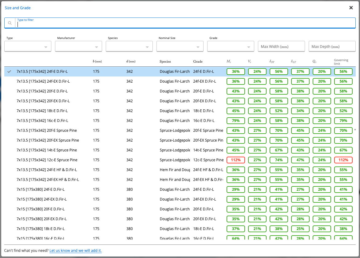
- Member type: Glulam, Douglas Fir
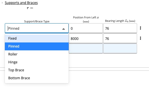
- Supports: Pinned and roller support on the left and right respectively, 75 mm bearing length
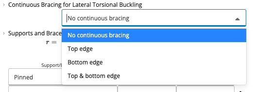
- Bracing: No continuous bracing
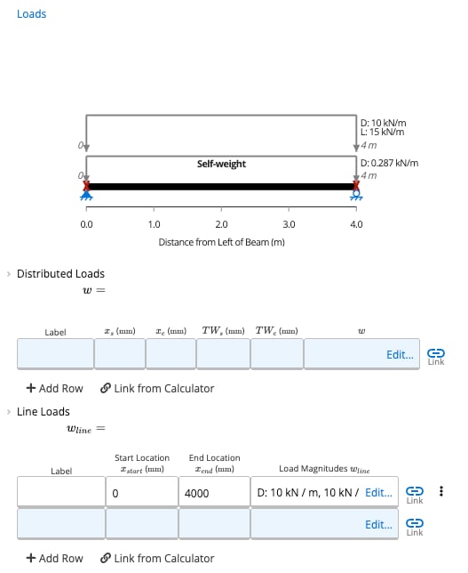
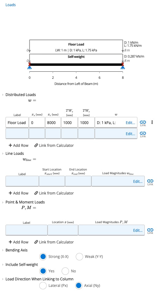
- Loads: 10 kN/m dead load and 15 kN/m live loads along the strong axis
- Self-weight included
- Dry service conditions, untreated with no load sharing
Open the Generic Beam preset
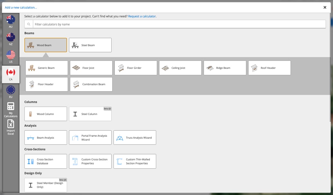
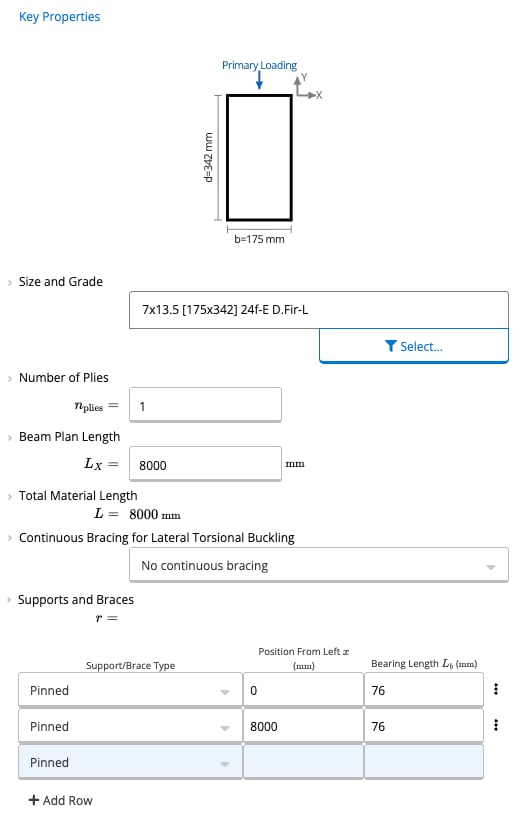
Check the member

Set the beam length

Set the supports
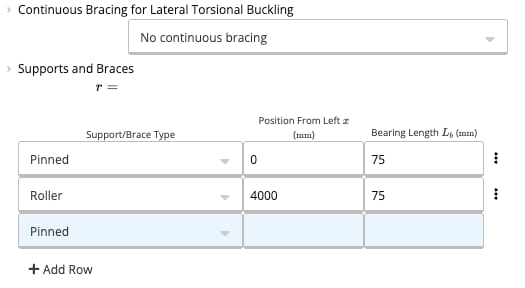
Remove the preset's distributed load
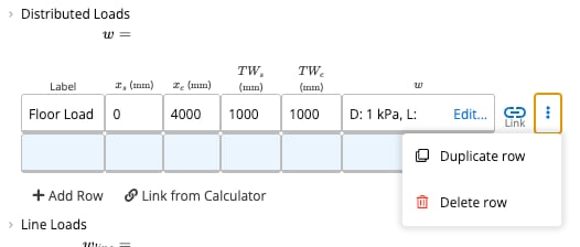
Add the line load
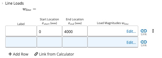
Enter the line load
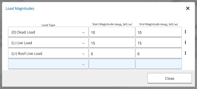
Check the rest of the loads
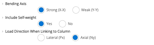
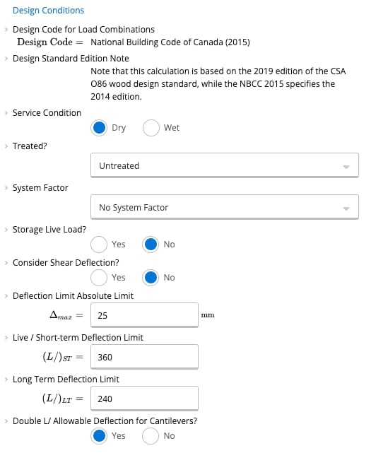
Check the design conditions
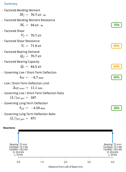
Read the results

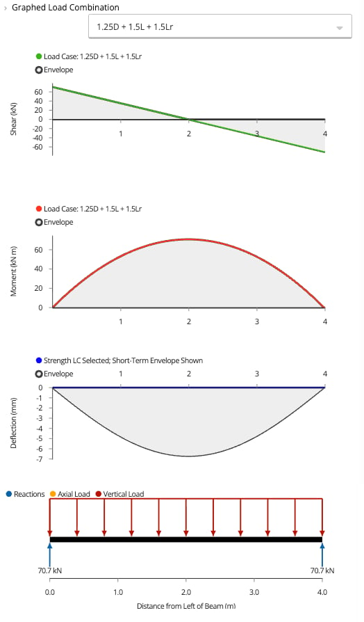
Look at the graphs
Inputs
Calcs.com output
Hand check
This is a sanity check on the demands and the reactions only. It uses the 1.25D + 1.5L + 1.5 combination shown on the graphs, with = 0 and L = 4 m, and the dead load from the sheet’s own load diagram. Calculator version 33, Generic Beam preset.
Method & scope
See the exact clause
Symbols
These are the symbols used on this page. The names for the sheet’s inputs and results are the labels the calculator shows; the others are as described in the sections below and in the calculator’s explanations.Calculation method
Structural model and load combinations
The calculator models the beam as a one-dimensional element and computes bending moment, shear, and deflection diagrams under each NBCC 2015 load combination. Loads are entered by type, dead (D), live (L), snow (S), wind (W), and the calculator automatically generates all governing strength (ULS) and serviceability (SLS) combinations, for example:- 1.25D + 1.5L
- 1.25D + 1.5S + 1.0L
- 0.9D + 1.5W (uplift check)
Bending moment resistance (CSA O86:19 Cl.7)
Factored bending resistance is computed from the reference bending strength adjusted by a chain of CSA O86:19 factors:- , system factor for repetitive-member assemblies
- , service-condition factor for bending
- , treatment factor
- , size factor for sawn lumber, or volume factor for glulam members
Shear resistance (CSA O86:19 Cl.6.5.4.3)
Factored shear resistance applies the service-condition, treatment, and size adjustment factors to the reference shear strength . For glulam members the calculator uses the CSA O86 simplified shear strength method, which is valid for members with volume under 2 m³. Shear demand is taken at the location of peak shear, which may conservatively be directly over the support rather than at distance d. shear utilizationBearing capacity
For each support, factored bearing demand is checked against factored bearing resistance , adjusted for service condition and treatment. A bearing contact area is specified per support; the check is skipped for supports with zero contact area.Deflection checks (CSA O86:19 Cl.5.4.2 / NBCC Commentary D)
Three independent deflection limits are verified per span:- Live/short-term deflection, governed by short-term serviceability load combinations; checked against a user-defined span/n ratio
- Long-term deflection, the elastic deflection under sustained dead load including self-weight; checked against a separate span/n ratio
- Simplified DL+LL deflection, total dead-plus-live deflection checked against a third span/n limit
Load linking
Support reactions are exported as linked outputs. When this beam is part of a larger project, connected column and footing calculations downstream automatically receive updated reactions whenever the beam inputs change, no manual re-entry of loads required.How to use it
Key Properties
Loads
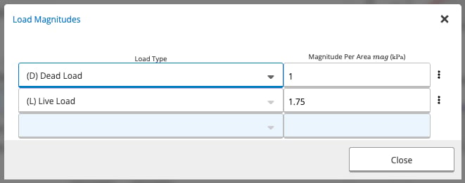
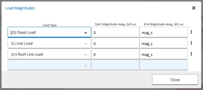
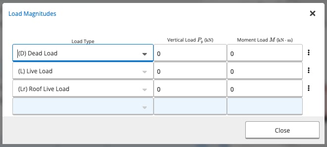
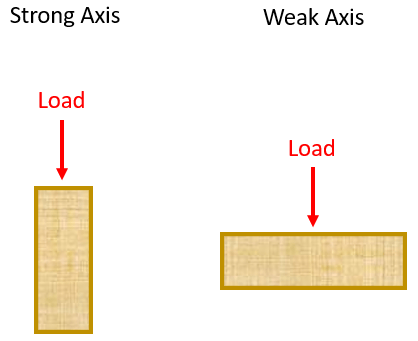
Design Conditions
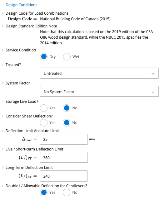
- Design Code for Load Combinations: Shows the design code used for the load combinations, the National Building Code of Canada (2015). It may be changed in the Project Defaults sheet for the project, and it cannot be changed in an individual calculation.
- Design Standard Edition Note: A note that the calculation is based on the 2019 edition of the CSA O86 wood design standard, while the NBCC 2015 specifies the 2014 edition.
- Service Condition: You need to indicate if the service condition is ‘dry’ or ‘wet.’ It is considered dry if the average equilibrium moisture content of the wood is 15% or less on average over a year without exceeding 19%. Wet service conditions are all other service conditions, and most often apply only to exterior use. Structural composite lumber (LVL, PSL, etc.) and I-joist products are usually not to be used in wet conditions. The service-condition factor appears in the Modulus of Elasticity, Bending Moment Resistance, Shear Resistance and Bearing sections as an adjustment factor.
- Treatment: Calcs.com requires you to indicate if the wood beam is untreated, or if it is preservative-treated and whether it is incised (partially cut) or unincised. The options are Untreated, Preservative-treated non-incised and Preservative-treated incised. The treatment factor depends on the incising and treatment of the lumber, and appears as an adjustment factor in the Modulus of Elasticity, Bending Moment Resistance, Shear Resistance and Bearing sections.
- System Factor: A system factor is considered if the member is part of a system where loads can be shared. There are three options for sawn lumber:
- No System Factor: There are less than 3 beams spaced 610 mm apart and/or are not mutually sharing loads
- Case 1 (for systems that don’t meet Case 2 requirements): There are more than 3 beams spaced less than 610 mm apart, mutually sharing loads
- Case 2 (typical for joists and rafters): All of the following conditions are met
- There are more than 3 beams spaced less than 610 mm apart, mutually sharing the load
- Members are sheathed with a minimum of 9.5 mm OSB, waferboard, plywood or with min. 17mm lumber with panel coverings.
- The sheathing is attached with sufficient stiffness and adequate spacing equal to 2 common nails at 150 mm on center at edges and 300 mm on center elsewhere.
- For glulam and SCL (LVL) products, there is no Case 1 or Case 2. The only condition is that the members are used in a load-sharing system of at least three parallel members with a maximum of 610 mm center-to-center spacing.
- Storage Live Load: A storage live load is a live load (loads due to occupancy use) that occurs for a long duration. An example of this is storage in an attic. If this is set to yes, the duration factor associated with live load will be taken the same as dead load, and the load factor on live load will be increased in some combinations. A long duration live load has a decreased load-duration factor of 0.65 () for load combinations of dead load plus live load only.
- Consider Shear Deflection: Shear deflection can be a significant component of total deflection due to the low shear modulus. In particular, specifications for structural composites such as LVL often require that shear deflection be directly accounted for. If this is set to “Yes”, we use an approximation based on the peak moment within a span to find the shear deflection. This gives exact results for simply supported and cantilever spans with either a point load in the center or a UDL.
- Absolute Deflection Limit: The maximum allowable deflection for the beam in millimeters (mm) or inches (in), regardless of span length. Normally, your local building code will dictate this.
- Live/Short-term Deflection Ratio: The maximum allowable deflection ratio for live and short loading, calculated independently for each span. The default is L/360 but you may change this to a preferred ratio.
- Long Term Deflection Ratio: The maximum allowable deflection ratio for long-term loading, calculated independently for each span. The default is L/240 but you may change this to a preferred ratio.
- Double Length/Allowable Deflection for Cantilevers: For cantilever spans, it’s typical to take “L” as double the span length. To adjust for this, the allowable deflection can be doubled.
Summary and Graphs

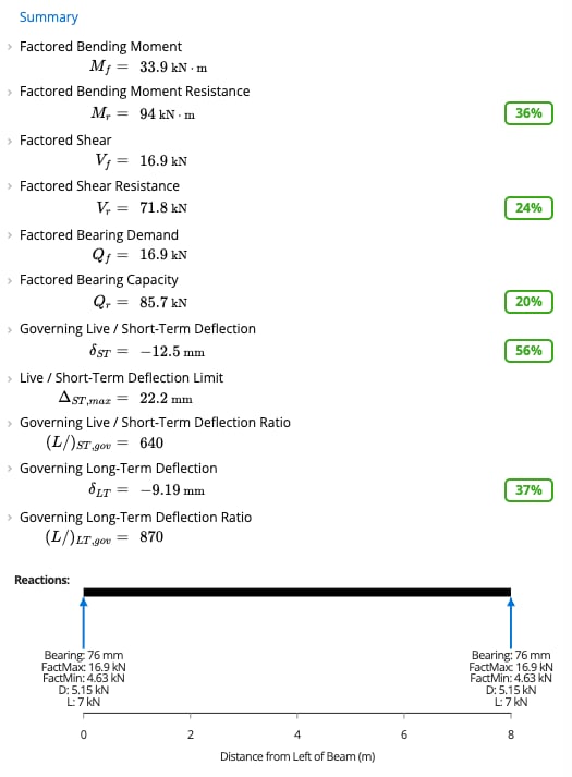
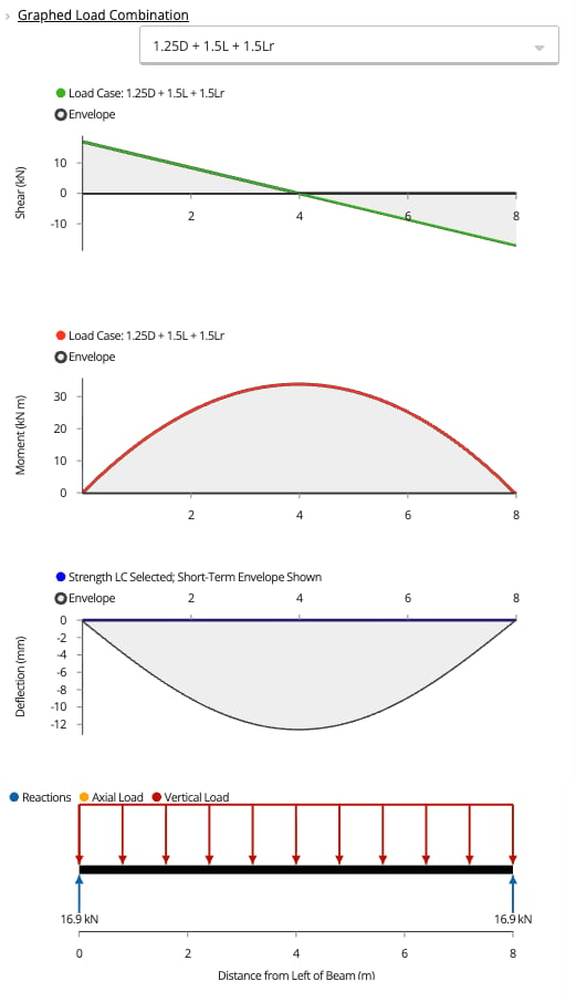
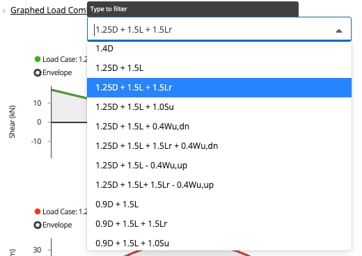
- Load Combination Analysis
- Unfactored Load Analysis
- Modulus of Elasticity (CSA O86:19 Section 6.3)
- Bending Moment Resistance (CSA O86:19 Section 6.5.3)
- Positive Bending (CSA O86:19 Section 6.5.3)
- Negative Bending (CSA O86:19 Section 6.5.3)
- Shear Resistance (CSA O86:19 Section 6.5.4)
- Bearing (Compressive Resistance Perpendicular to Grain) (CSA O86:19 Section 6.5.6)
- Deflections
Available presets
Each preset opens the calculator with a typical setup already entered.Common questions
What design standard does this calculator use?
What design standard does this calculator use?
What are the key inputs?
What are the key inputs?
What checks and outputs does it produce?
What checks and outputs does it produce?
Can it handle multi-ply beams and glulam?
Can it handle multi-ply beams and glulam?
How do I select a wood section?
How do I select a wood section?
Does this calculator support load linking with column and footing calculations?
Does this calculator support load linking with column and footing calculations?