> ## Documentation Index
> Fetch the complete documentation index at: https://calcs.com/docs/llms.txt
> Use this file to discover all available pages before exploring further.
# How to Design an Inclined Member in Calcs.com
> Set slope, choose plan or inclined view, and pick a load orientation to design rafters, hip beams, and other inclined members in Calcs.com.
When working with roof elements such as rafters, hip beams, or valley beams, you may need to model a structural member that sits on an incline. Calcs.com makes this easy using built-in presets and flexible input controls. This article walks through how to set up and design an inclined member from scratch.
***
Follow along below or with this video:
## **Starting a Beam Calculation**
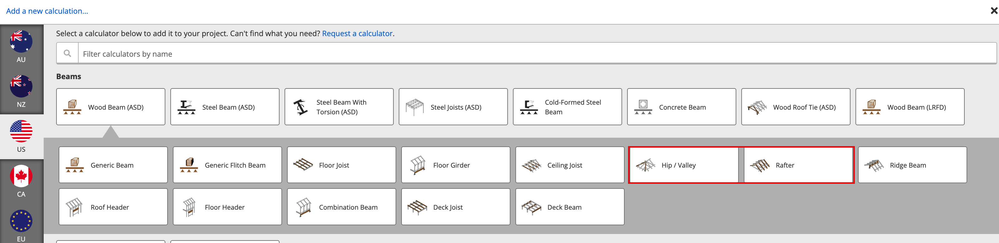
If you're designing a beam, Calcs.com includes several presets specifically for roof elements, including the **Hip/Valley Beam or Rafter.**
These presets automatically apply an incline.\
However, you can also start with a **Generic Beam** and define your own slope.
 ***
## **Setting the Beam Incline**
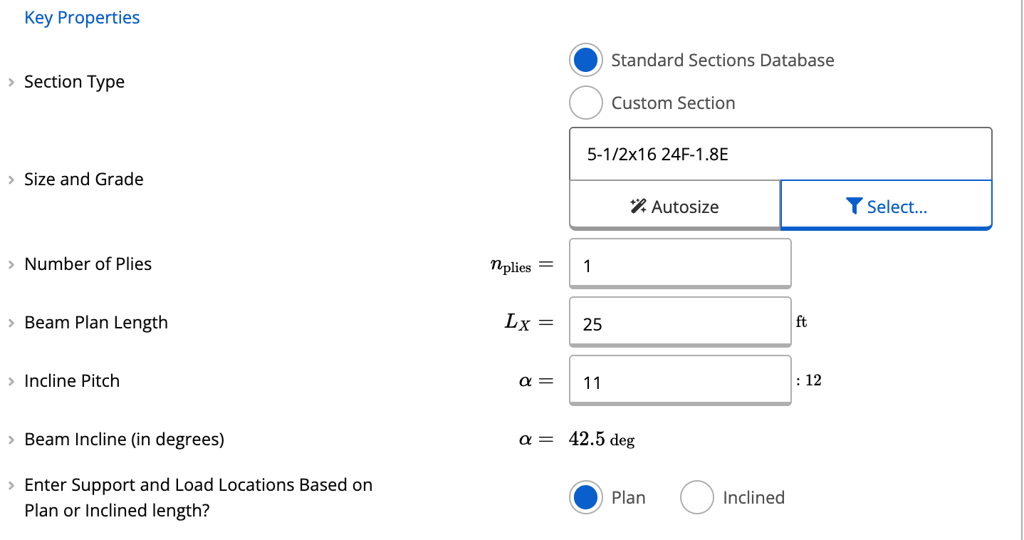
In any beam calculation, you can set a sloped condition that allows you to input the incline pitch, as shown below. By default, a generic beam is assumed to have no slope, so we need to indicate this in our design conditions.
***
## **Setting the Beam Incline**
In any beam calculation, you can set a sloped condition that allows you to input the incline pitch, as shown below. By default, a generic beam is assumed to have no slope, so we need to indicate this in our design conditions.
 ### **Where to Find Slope Settings**
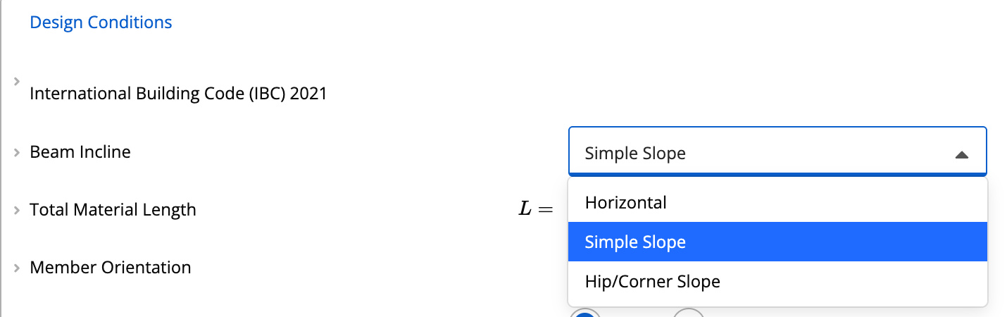
Scroll down to the **Design Conditions** section.\
Under **Beam Incline Type**, choose from:
* **Simple Slope** – defines a single plane incline (most common)
* **Hip or Corner Slope** – for beams sloping in two directions
### **Where to Find Slope Settings**
Scroll down to the **Design Conditions** section.\
Under **Beam Incline Type**, choose from:
* **Simple Slope** – defines a single plane incline (most common)
* **Hip or Corner Slope** – for beams sloping in two directions
 ### **Entering Your Slope**
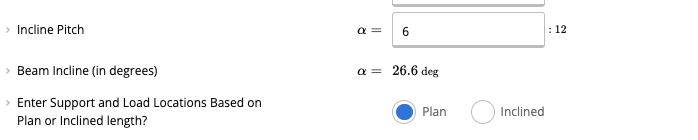
When **Simple Slope** is selected, additional inputs will appear allowing you to define the incline.
You can enter slope in two ways:
* **Rise/Run (e.g., 11:12)**
* The software automatically converts this to **degrees**
This ensures your beam geometry is modeled accurately.
***
## **Choosing How to Enter Support and Load Locations**
After defining the incline, choose how you want to input beam geometry and loads:
* **Plan View** – distances measured horizontally based on the plan length
* **Inclined View** – distances measured along the slope of the beam
Switching between these modes updates the input fields to match your preferred workflow.
### **Entering Your Slope**
When **Simple Slope** is selected, additional inputs will appear allowing you to define the incline.
You can enter slope in two ways:
* **Rise/Run (e.g., 11:12)**
* The software automatically converts this to **degrees**
This ensures your beam geometry is modeled accurately.
***
## **Choosing How to Enter Support and Load Locations**
After defining the incline, choose how you want to input beam geometry and loads:
* **Plan View** – distances measured horizontally based on the plan length
* **Inclined View** – distances measured along the slope of the beam
Switching between these modes updates the input fields to match your preferred workflow.
 ***
## **Defining Loads on the Inclined Beam**
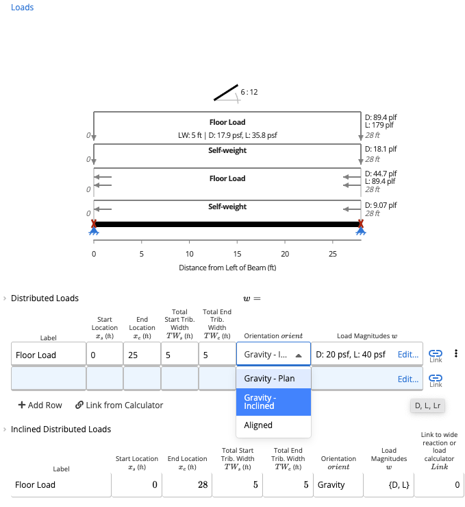
Calcs.com gives you flexibility in how loads are interpreted:
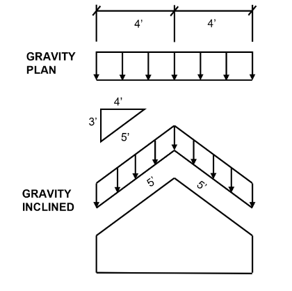
* **Gravity - Plan** - loads applied over the plan length, meaning the horizontal projection of the structure
* **Gravity - Incline -** loads applied over the inclined length, meaning the actual sloped length of the structure
* **Beam-Aligned Loads** - applied directly along the sloped member
You can specify line loads, point loads, or distributed loads as usual.
The interface includes additional notes explaining how loads are resolved into components on the beam.
***
## **Defining Loads on the Inclined Beam**
Calcs.com gives you flexibility in how loads are interpreted:
* **Gravity - Plan** - loads applied over the plan length, meaning the horizontal projection of the structure
* **Gravity - Incline -** loads applied over the inclined length, meaning the actual sloped length of the structure
* **Beam-Aligned Loads** - applied directly along the sloped member
You can specify line loads, point loads, or distributed loads as usual.
The interface includes additional notes explaining how loads are resolved into components on the beam.
 ***
## **Linking Loads to the Beam**
Once the beam is inclined:
* Linked loads will automatically account for slope effects
* Reactions and internal forces are calculated using the true geometry
This ensures accurate analysis of bending, shear, and axial forces resulting from the incline.
***
## Load orientation: Gravity vs. horizontal-projected load
The single most common reason a sloped-member result — a rafter, rafter tie, hip beam, or any other inclined member — won't match a hand calculation is a mismatch between how the load is applied in the calculator versus how it was resolved in the hand check. Both bases are internally consistent. You just need to know which one you're using.
Under **Load Orientation**, the **Gravity - Incline** setting applies the entered psf (or plf) load over the **sloped length** of the member, not over the horizontal projection. If your hand calc resolved the roof load onto the **horizontal projected area** and then compared it to a Calcs.com result that used **Gravity - Incline**, the two will not match — the Calcs.com result will be larger by roughly a factor of 1/cos(slope), because the same psf is being applied to a longer surface.
A quick way to sanity-check yourself: if you entered a snow or dead load as psf from the code (which is typically defined on the **horizontal projected area** of the roof), use **Gravity - Plan** so the calculator matches that definition. Use **Gravity - Incline** when the load intensity you're entering is genuinely defined per unit of sloped surface (e.g. some roofing self-weights supplied by a manufacturer along the slope).
The three options behave as follows:
* **Gravity - Plan** — the entered load acts over the **plan (horizontal) length** of the member. This matches code-defined roof snow, dead, and live loads applied to the horizontal projected area.
* **Gravity - Incline** — the entered load acts over the **actual sloped length** of the member. Use this when the load intensity is defined per unit of sloped surface.
* **Beam-Aligned Loads** — the load acts directly along the member axis (not resolved from vertical gravity). Use this for point loads or line loads already given in the member's local coordinate system.
### Reconciling with a hand calc
If your hand check doesn't match the Calcs.com result on an inclined member, work through this in order:
1. Confirm which basis your hand calc used — **horizontal projection** or **sloped length**.
2. Open the calculator's **Load Orientation** setting and confirm it matches. If your hand calc used the horizontal projection, set **Gravity - Plan**.
3. Re-run and compare. If the numbers now agree in magnitude, the discrepancy was purely the load-orientation basis.
4. If they still disagree, check the entered slope (rise:run vs. degrees) and whether the load was entered as psf over tributary width vs. as a plf line load — those are the next two most common sources of mismatch.
### Where this applies
This distinction applies to **any Calcs.com calculator that supports inclined or sloped members**, including:
* **Wood Beam** with a **Generic Beam** or **Hip/Valley Beam or Rafter** preset and an incline set
* **Rafter Tie** and other roof-tie calculators
* **Steel Beam** when configured on an incline
* Any other member calculator with a **Simple Slope** or **Hip or Corner Slope** setting
## Related
* [How to Design a Wood Beam, including Joists, Rafters, and Ridge Beams to NDS 2018](https://calcs.com/docs/calculators/beams/us/how-to-design-wood-beam-including-joists-rafters-ridge-beams)
* [Linking Loads and Reactions Between Calculators (Load Path Tracking)](https://calcs.com/docs/running-calculations/linking-loads/linking-loads-reactions-between-calculators-load-path-tracking)
* [What is tributary width?](https://calcs.com/docs/running-calculations/setting-up-a-calculation/loads/what-is-tributary-width)
***
## **Linking Loads to the Beam**
Once the beam is inclined:
* Linked loads will automatically account for slope effects
* Reactions and internal forces are calculated using the true geometry
This ensures accurate analysis of bending, shear, and axial forces resulting from the incline.
***
## Load orientation: Gravity vs. horizontal-projected load
The single most common reason a sloped-member result — a rafter, rafter tie, hip beam, or any other inclined member — won't match a hand calculation is a mismatch between how the load is applied in the calculator versus how it was resolved in the hand check. Both bases are internally consistent. You just need to know which one you're using.
Under **Load Orientation**, the **Gravity - Incline** setting applies the entered psf (or plf) load over the **sloped length** of the member, not over the horizontal projection. If your hand calc resolved the roof load onto the **horizontal projected area** and then compared it to a Calcs.com result that used **Gravity - Incline**, the two will not match — the Calcs.com result will be larger by roughly a factor of 1/cos(slope), because the same psf is being applied to a longer surface.
A quick way to sanity-check yourself: if you entered a snow or dead load as psf from the code (which is typically defined on the **horizontal projected area** of the roof), use **Gravity - Plan** so the calculator matches that definition. Use **Gravity - Incline** when the load intensity you're entering is genuinely defined per unit of sloped surface (e.g. some roofing self-weights supplied by a manufacturer along the slope).
The three options behave as follows:
* **Gravity - Plan** — the entered load acts over the **plan (horizontal) length** of the member. This matches code-defined roof snow, dead, and live loads applied to the horizontal projected area.
* **Gravity - Incline** — the entered load acts over the **actual sloped length** of the member. Use this when the load intensity is defined per unit of sloped surface.
* **Beam-Aligned Loads** — the load acts directly along the member axis (not resolved from vertical gravity). Use this for point loads or line loads already given in the member's local coordinate system.
### Reconciling with a hand calc
If your hand check doesn't match the Calcs.com result on an inclined member, work through this in order:
1. Confirm which basis your hand calc used — **horizontal projection** or **sloped length**.
2. Open the calculator's **Load Orientation** setting and confirm it matches. If your hand calc used the horizontal projection, set **Gravity - Plan**.
3. Re-run and compare. If the numbers now agree in magnitude, the discrepancy was purely the load-orientation basis.
4. If they still disagree, check the entered slope (rise:run vs. degrees) and whether the load was entered as psf over tributary width vs. as a plf line load — those are the next two most common sources of mismatch.
### Where this applies
This distinction applies to **any Calcs.com calculator that supports inclined or sloped members**, including:
* **Wood Beam** with a **Generic Beam** or **Hip/Valley Beam or Rafter** preset and an incline set
* **Rafter Tie** and other roof-tie calculators
* **Steel Beam** when configured on an incline
* Any other member calculator with a **Simple Slope** or **Hip or Corner Slope** setting
## Related
* [How to Design a Wood Beam, including Joists, Rafters, and Ridge Beams to NDS 2018](https://calcs.com/docs/calculators/beams/us/how-to-design-wood-beam-including-joists-rafters-ridge-beams)
* [Linking Loads and Reactions Between Calculators (Load Path Tracking)](https://calcs.com/docs/running-calculations/linking-loads/linking-loads-reactions-between-calculators-load-path-tracking)
* [What is tributary width?](https://calcs.com/docs/running-calculations/setting-up-a-calculation/loads/what-is-tributary-width)