> ## Documentation Index
> Fetch the complete documentation index at: https://calcs.com/docs/llms.txt
> Use this file to discover all available pages before exploring further.
# Wind Loads (ASCE 7-22) - Components and Cladding Overview
> Overview of the ASCE 7-22 Wind Loads calculator for Components and Cladding
**Instantly create a new Wind Loads (Components and Cladding) calculation by clicking here:**
[**Create Wind Loads Calculator**](https://calcs.com/new/sheet/loadsWindCnCASCE7-22?presetCode=Components+and+Cladding)
*(This link automatically opens a new project and sheet in Calcs.com.)*
# Background
The Calcs.com Wind Load Calculator for Components and Cladding (C\&C) provides a streamlined and accurate solution for calculating wind pressures in accordance with **ASCE 7-22 Chapter 30**. This calculator helps structural engineers quickly determine design wind pressures acting on specific building elements (such as purlins, girts, studs, and roof decking) and cladding, taking into account a wide range of building configurations, exposure conditions, and the new tornado load requirements introduced in ASCE 7-22.
The calculator determines the required corner, edge, and field zones, wind pressure coefficients, and resulting design pressures, providing a comprehensive analysis for various design scenarios including Enclosed, Partially Enclosed, Partially Open, and Open buildings.
**Want to learn more?** Check out our [Wind Load Calculations to American Standards webinar](https://calcs.com/webinars/wind-loads-residential) to learn how to analyze wind load requirements for residential buildings based on the American Standards, including worked examples using our wind load calculators.
# Project Defaults
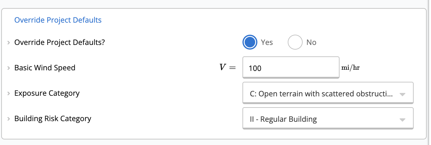
You can select whether the calculator will use the project defaults, where you can set the building code used for your project, as well as wind, snow, seismic, and general criteria.
In particular, if you provide the project address in the Project Details as well as the **Risk Category** and **Exposure Category**, the basic wind speed and ground elevation will be automatically determined and used in your wind calculator.
If you select to **Override Project Defaults**, you must manually input the following:
* **Basic Wind Speed (V)**
* **Exposure Category** (B, C, or D)
* **Building Risk Category** (I, II, III, or IV)
* **Tornado-Prone Region status**
* **Tornado Speed (V\_T)** (if applicable)
 # Key Properties
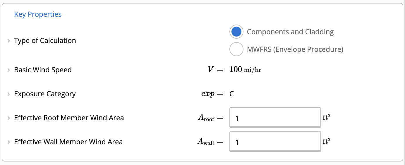
Under the key properties section, you can select **Type of Calculation**. For this article, we focus on **Components and Cladding**.
* **Effective Roof Member Wind Area** and **Effective Wall Member Wind Area**: tributary area of the member being designed (for example, a single roof truss or wall stud). These values set external pressure coefficients ($GC_p$) when **Individual Effective Area per Wind Zone** is **No**.
* **Individual Effective Area per Wind Zone**: set to **Yes** to define different effective areas in the **Individual Effective Area** table for each zone. Parapet inputs are hidden when this is **Yes**.
# Key Properties
Under the key properties section, you can select **Type of Calculation**. For this article, we focus on **Components and Cladding**.
* **Effective Roof Member Wind Area** and **Effective Wall Member Wind Area**: tributary area of the member being designed (for example, a single roof truss or wall stud). These values set external pressure coefficients ($GC_p$) when **Individual Effective Area per Wind Zone** is **No**.
* **Individual Effective Area per Wind Zone**: set to **Yes** to define different effective areas in the **Individual Effective Area** table for each zone. Parapet inputs are hidden when this is **Yes**.
 # Building Properties
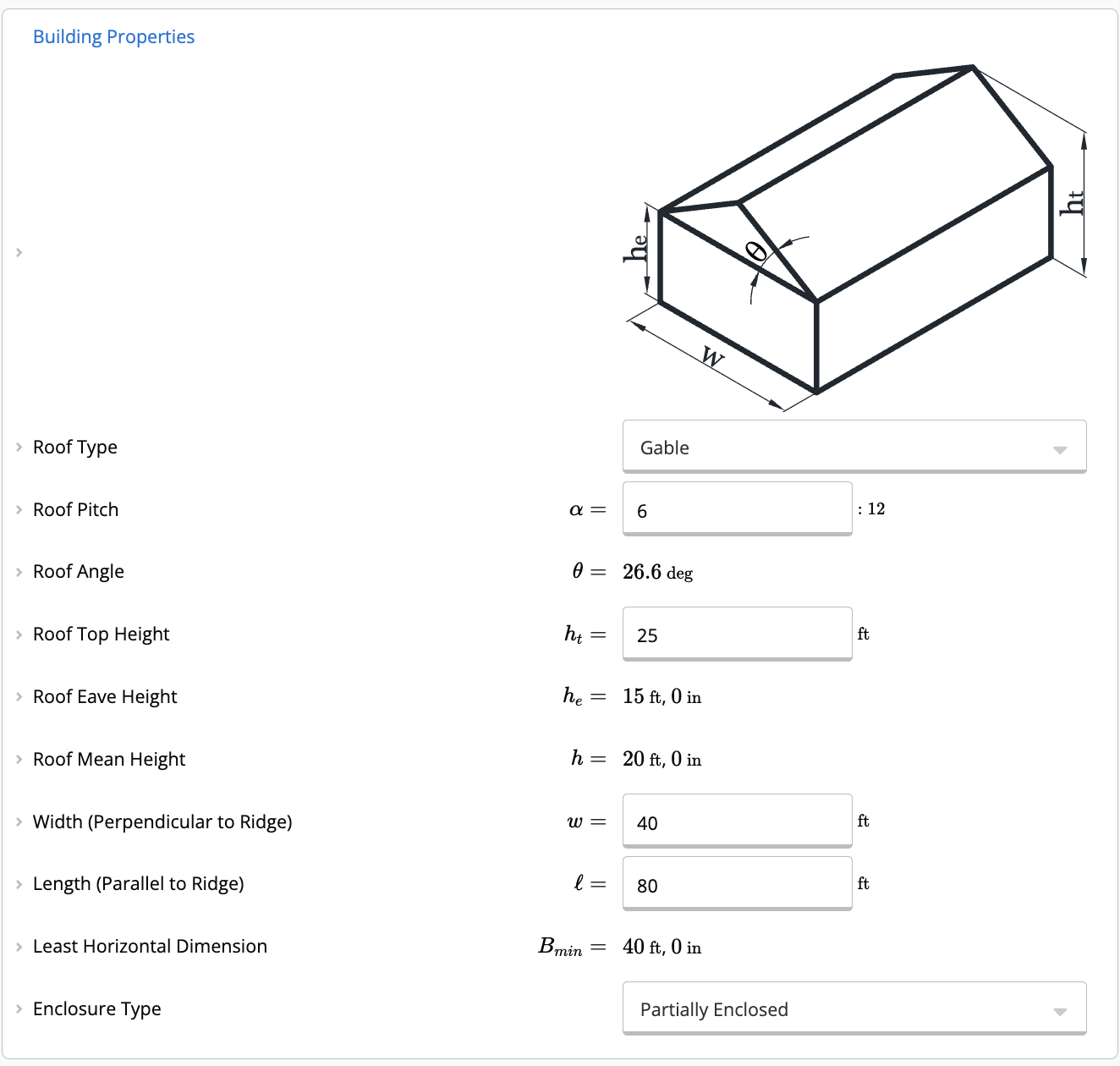
This input allows you to define the geometry and enclosure classification of the structure.
* **Roof Type:** Supported roof types include **Flat**, **Gable**, **Hip**, and **Monoslope**.
* Depending on the selection, you will define properties such as **Roof Pitch**, **Roof Top Height** ($h_t$), and **Eave Height** ($h_e$).
* **Dimensions:** Define the Building Width ($w$) and Length ($l$).
* **Enclosure Type:**
* **Enclosed:** A structure with controlled openings (e.g., typical office buildings).
* **Partially Enclosed:** A structure with large openings on one wall causing internal pressure buildup (e.g., a warehouse with a large open door during a storm).
* **Partially Open:** A structure with significant openings on multiple walls.
* **Open:** A structure with no walls, where wind flows freely over and under the roof (e.g., carports, canopies, agricultural sheds, and covered pavilions). For Open enclosures, the calculator uses free-roof net pressure coefficients ($C_N$) per **Cl. 30.5**, tabulated across interior, edge, and corner wind zones with three effective-wind-area bands per zone. Per Note 3 on the governing figures, interpolation is permitted only on roof angle ($\theta$), never on effective wind area. A minimum net design pressure of **16 psf** is enforced per Cl. 30.2.2. Open enclosure support is currently limited to **monoslope** and **gable** roof shapes, with a single effective wind area applied uniformly across all zones.
* **Large-Volume, Unpartitioned Building?** (appears when Enclosure Type is **Partially Enclosed**): set to **Yes** for a single, unpartitioned large-volume building such as an arena, aircraft hangar, or open-interior warehouse. This exposes **Unpartitioned Internal Volume** ($V_i$) and **Total Area of Envelope Openings** ($A_{og}$), and applies the Internal Pressure Reduction Factor $R_i$ per Eq. 26.13-1 to $GC_{pi}$. Defaults to no reduction ($R_i = 1.0$).
**Tornado loads with Open enclosures**
On ASCE 7-22 sheets, the Chapter 32 tornado load tables are not displayed for Open enclosures because that procedure is not yet implemented for free roofs. See the in-calculator note for the current scope.
# Building Properties
This input allows you to define the geometry and enclosure classification of the structure.
* **Roof Type:** Supported roof types include **Flat**, **Gable**, **Hip**, and **Monoslope**.
* Depending on the selection, you will define properties such as **Roof Pitch**, **Roof Top Height** ($h_t$), and **Eave Height** ($h_e$).
* **Dimensions:** Define the Building Width ($w$) and Length ($l$).
* **Enclosure Type:**
* **Enclosed:** A structure with controlled openings (e.g., typical office buildings).
* **Partially Enclosed:** A structure with large openings on one wall causing internal pressure buildup (e.g., a warehouse with a large open door during a storm).
* **Partially Open:** A structure with significant openings on multiple walls.
* **Open:** A structure with no walls, where wind flows freely over and under the roof (e.g., carports, canopies, agricultural sheds, and covered pavilions). For Open enclosures, the calculator uses free-roof net pressure coefficients ($C_N$) per **Cl. 30.5**, tabulated across interior, edge, and corner wind zones with three effective-wind-area bands per zone. Per Note 3 on the governing figures, interpolation is permitted only on roof angle ($\theta$), never on effective wind area. A minimum net design pressure of **16 psf** is enforced per Cl. 30.2.2. Open enclosure support is currently limited to **monoslope** and **gable** roof shapes, with a single effective wind area applied uniformly across all zones.
* **Large-Volume, Unpartitioned Building?** (appears when Enclosure Type is **Partially Enclosed**): set to **Yes** for a single, unpartitioned large-volume building such as an arena, aircraft hangar, or open-interior warehouse. This exposes **Unpartitioned Internal Volume** ($V_i$) and **Total Area of Envelope Openings** ($A_{og}$), and applies the Internal Pressure Reduction Factor $R_i$ per Eq. 26.13-1 to $GC_{pi}$. Defaults to no reduction ($R_i = 1.0$).
**Tornado loads with Open enclosures**
On ASCE 7-22 sheets, the Chapter 32 tornado load tables are not displayed for Open enclosures because that procedure is not yet implemented for free roofs. See the in-calculator note for the current scope.
 # Terrain Properties
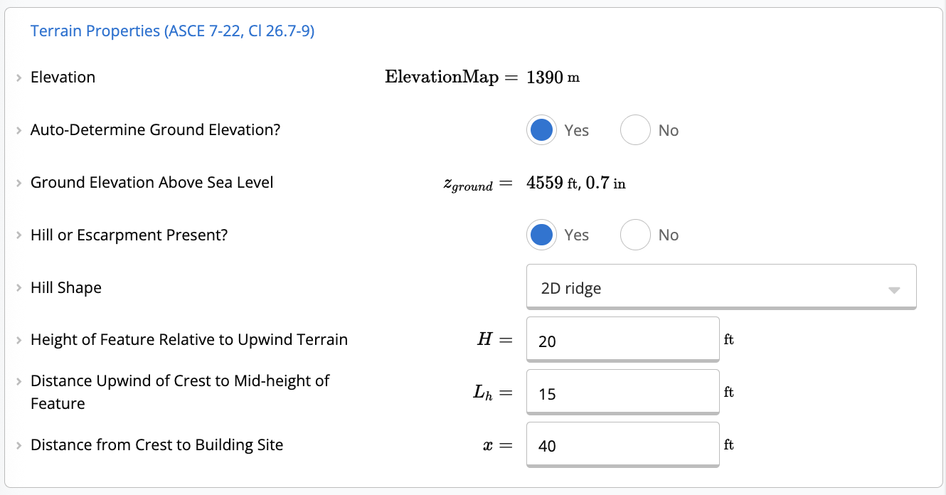
The calculator can automatically determine the **Ground Elevation Above Sea Level** if a project address is provided, calculating the Ground Elevation Factor ($K_e$) per ASCE 7-22 Section 26.9. Alternatively, a custom elevation can be entered.
**Topographic Effects:** If the site is located on a hill, ridge, or escarpment, you can toggle **Hill or Escarpment Present?** to "Yes". You must then select the **Hill Shape** (2D Ridge, 2D Escarpment, or 3D Axisymmetrical Hill) and provide:
* **H:** Height of feature relative to upwind terrain.
* **L\_h:** Distance upwind of crest to mid-height of feature.
* **x:** Distance from crest to building site.
These inputs calculate the Topographic Factor ($K_{zt}$) per ASCE 7-22 Section 26.8.
# Terrain Properties
The calculator can automatically determine the **Ground Elevation Above Sea Level** if a project address is provided, calculating the Ground Elevation Factor ($K_e$) per ASCE 7-22 Section 26.9. Alternatively, a custom elevation can be entered.
**Topographic Effects:** If the site is located on a hill, ridge, or escarpment, you can toggle **Hill or Escarpment Present?** to "Yes". You must then select the **Hill Shape** (2D Ridge, 2D Escarpment, or 3D Axisymmetrical Hill) and provide:
* **H:** Height of feature relative to upwind terrain.
* **L\_h:** Distance upwind of crest to mid-height of feature.
* **x:** Distance from crest to building site.
These inputs calculate the Topographic Factor ($K_{zt}$) per ASCE 7-22 Section 26.8.
 # Tornado Load Parameters (ASCE 7-22 Chapter 32)
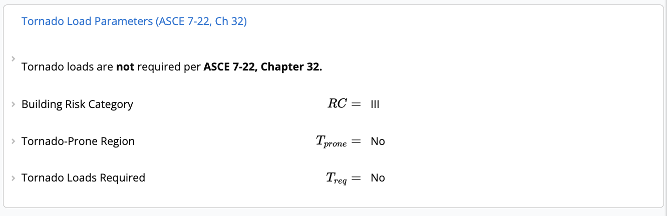
A significant addition to ASCE 7-22 is the requirement to check for Tornado Loads (Chapter 32). The calculator automatically performs the applicability check based on:
1. **Risk Category:** Generally applies to Risk Category III and IV structures (and some others depending on parameters).
2. **Tornado-Prone Region:** Whether the site is mapped in the tornado-prone region (Fig 32.1-1).
3. **Tornado Speed:** Compares the effective Tornado Speed ($V_T$) against the Basic Wind Speed ($V$).
If **Tornado Loads Required** calculates to "Yes", the calculator will generate a specific **Design Tornado Pressures** table alongside standard wind pressures.
**Want to learn more about tornado loads?** Check out our [Tornado Loads (ASCE 7-22) article](https://calcs.com/docs/calculations/us/tornado_loads_asce7_22) for detailed information on tornado load calculations and requirements.
# Tornado Load Parameters (ASCE 7-22 Chapter 32)
A significant addition to ASCE 7-22 is the requirement to check for Tornado Loads (Chapter 32). The calculator automatically performs the applicability check based on:
1. **Risk Category:** Generally applies to Risk Category III and IV structures (and some others depending on parameters).
2. **Tornado-Prone Region:** Whether the site is mapped in the tornado-prone region (Fig 32.1-1).
3. **Tornado Speed:** Compares the effective Tornado Speed ($V_T$) against the Basic Wind Speed ($V$).
If **Tornado Loads Required** calculates to "Yes", the calculator will generate a specific **Design Tornado Pressures** table alongside standard wind pressures.
**Want to learn more about tornado loads?** Check out our [Tornado Loads (ASCE 7-22) article](https://calcs.com/docs/calculations/us/tornado_loads_asce7_22) for detailed information on tornado load calculations and requirements.
 # Calculations and Results
Once all properties are defined, the calculator determines the following parameters per ASCE 7-22:
* **Velocity Pressure** ($q_h$): based on wind speed, exposure, ground elevation factor ($K_e$), and topography ($K_{zt}$).
* **Internal Pressure Coefficient** ($GC_{pi}$): based on enclosure type. For **Partially Enclosed** buildings, the Internal Pressure Reduction Factor $R_i$ (Eq. 26.13-1) can be applied when the building is a single, unpartitioned large volume.
* **External Pressure Coefficients** ($GC_p$): based on effective wind area and zone (corner, edge, field).
### Zones Diagram
A dynamic diagram visualizes the zones on the roof and walls, helping you identify where specific pressures apply.
# Calculations and Results
Once all properties are defined, the calculator determines the following parameters per ASCE 7-22:
* **Velocity Pressure** ($q_h$): based on wind speed, exposure, ground elevation factor ($K_e$), and topography ($K_{zt}$).
* **Internal Pressure Coefficient** ($GC_{pi}$): based on enclosure type. For **Partially Enclosed** buildings, the Internal Pressure Reduction Factor $R_i$ (Eq. 26.13-1) can be applied when the building is a single, unpartitioned large volume.
* **External Pressure Coefficients** ($GC_p$): based on effective wind area and zone (corner, edge, field).
### Zones Diagram
A dynamic diagram visualizes the zones on the roof and walls, helping you identify where specific pressures apply.
 ### Wind Pressure Results
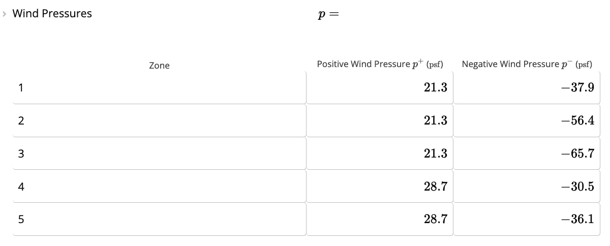
The summary section provides a table listing the **Design Wind Pressures** for each zone.
* **Zone:** Identifies the specific area (e.g., Zone 1, 2, 3 for roofs; 4, 5 for walls).
* **Positive/Negative Pressure:** The design pressure ($p$) calculated as: $p = q_h [ (GC_p) - (GC_{pi}) ]$
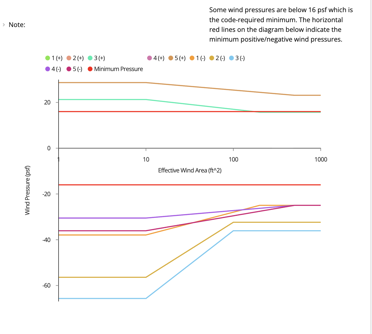
* **Minimum Loads:** ASCE 7-22 imposes a minimum wind pressure of **16 psf**. The calculator automatically compares calculated values and defaults to 16 psf if the calculated pressure is lower.
### Wind Pressure Results
The summary section provides a table listing the **Design Wind Pressures** for each zone.
* **Zone:** Identifies the specific area (e.g., Zone 1, 2, 3 for roofs; 4, 5 for walls).
* **Positive/Negative Pressure:** The design pressure ($p$) calculated as: $p = q_h [ (GC_p) - (GC_{pi}) ]$
* **Minimum Loads:** ASCE 7-22 imposes a minimum wind pressure of **16 psf**. The calculator automatically compares calculated values and defaults to 16 psf if the calculated pressure is lower.
 If Tornado Loads are applicable, a separate table **Design Tornado Pressures** will appear, displaying pressures ($p_T$) adjusted by the Tornado Directionality Factor ($K_{dT}$) and Tornado Pressure Coefficient Adjustment Factors ($K_{vT}$).
### Strength-level pressures: no manual ASD conversion needed
Calcs.com uses the **same strength-level Components and Cladding wind pressure** in both **LRFD** and **ASD** member calculators. The ASD load combinations apply the **0.6W** factor internally, so you should enter the C\&C pressures **as-is regardless of which calculator you are working in** — do not manually multiply by 0.6 before entering them.
Manual conversion only comes into play if you are bringing in **ASD or nominal wind values from outside Calcs.com** (for example, from a separate wind report already presented at ASD level). In that case, convert those external values back up to strength level before entering them, so the ASD combinations apply the 0.6W factor once and only once.
For MWFRS Directional Procedure loads (Chapter 27), see [Wind Loads - MWFRS Directional Procedure (ASCE 7-16 and ASCE 7-22)](/docs/calculations/us/wind_loads_mwfrs_directional_asce_7).
For parapet wind pressures on MWFRS or C\&C sheets, see [Wind Load Parapets (ASCE 7-16 and ASCE 7-22)](/docs/calculations/us/wind_loads_parapets_asce_7).
If Tornado Loads are applicable, a separate table **Design Tornado Pressures** will appear, displaying pressures ($p_T$) adjusted by the Tornado Directionality Factor ($K_{dT}$) and Tornado Pressure Coefficient Adjustment Factors ($K_{vT}$).
### Strength-level pressures: no manual ASD conversion needed
Calcs.com uses the **same strength-level Components and Cladding wind pressure** in both **LRFD** and **ASD** member calculators. The ASD load combinations apply the **0.6W** factor internally, so you should enter the C\&C pressures **as-is regardless of which calculator you are working in** — do not manually multiply by 0.6 before entering them.
Manual conversion only comes into play if you are bringing in **ASD or nominal wind values from outside Calcs.com** (for example, from a separate wind report already presented at ASD level). In that case, convert those external values back up to strength level before entering them, so the ASD combinations apply the 0.6W factor once and only once.
For MWFRS Directional Procedure loads (Chapter 27), see [Wind Loads - MWFRS Directional Procedure (ASCE 7-16 and ASCE 7-22)](/docs/calculations/us/wind_loads_mwfrs_directional_asce_7).
For parapet wind pressures on MWFRS or C\&C sheets, see [Wind Load Parapets (ASCE 7-16 and ASCE 7-22)](/docs/calculations/us/wind_loads_parapets_asce_7).